
Radiographic tomography apparatus

a tomography and radiography technology, applied in the field of radiography tomography apparatus, can solve the problems of unsatisfactory radiographic image of an examinee, failure to reveal anything concerning such other body motions, etc., and achieve the effect of increasing measurement accuracy

Active Publication Date: 2013-01-29
FUJIFILM CORP
View PDF6 Cites 2 Cited by
  • Summary
  • Abstract
  • Description
  • Claims
  • Application Information

AI Technical Summary

Benefits of technology

The present invention is about a radiographic tomography apparatus that can improve the accuracy of measurements. It does this by detecting body motion of the examinee using still images at different times. This helps to determine the reliability of the tomosynthetic tomography images captured by the apparatus. The apparatus may also include a body motion indicator that alerts the user when there is significant body motion and that may prevent accurate measurements. This makes it easier for the user to recognize when there is body motion and take appropriate action.

Problems solved by technology

In a radiographic imaging process, a satisfactory radiographic image of an examinee may not be captured if the body of the examinee moves too much, or if the region of the examinee that is to be imaged significantly changes in position.
U.S. Pat. No. 7,127,028 B2, however, also fails to reveal anything concerning such other body motions.

Method used


Image

  • Radiographic tomography apparatus
  • Radiographic tomography apparatus
  • Radiographic tomography apparatus

Examples


first embodiment

A. First Embodiment

1. Configuration of Radiographic Tomography Apparatus 10

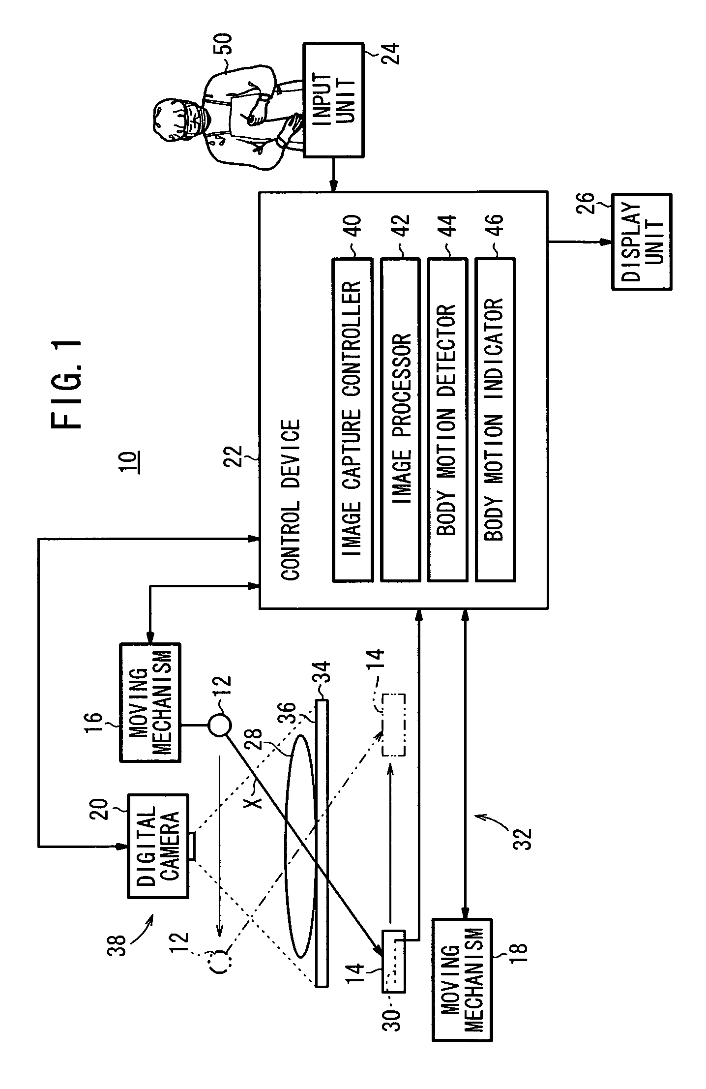
[0025]FIG. 1 shows in block form a radiographic tomography apparatus 10 according to a first embodiment of the present invention. As shown in FIG. 1, the radiographic tomography apparatus 10 comprises a radiation source 12, a cassette 14, a first moving mechanism 16, a second moving mechanism 18, a digital camera 20, a control device 22, an input unit 24, and a display unit 26.

[0026]The radiation source 12 emits a given radiation X, such as X-rays or the like, at a given dose in response to a command from the control device 22. The cassette 14 houses therein a radiation conversion panel 30, which detects the radiation X emitted from the radiation source 12 and transmitted through an examinee (patient) 28, and converts the detected radiation X into radiographic image information. The radiation conversion panel 30 outputs the radiographic image information to the control device 22. The first moving mechanism 16...

second embodiment

B. Second Embodiment

1. Differences from the First Embodiment

[0047]FIG. 3 shows in block form a radiographic tomography apparatus 10A according to a second embodiment of the present invention. As shown in FIG. 3, the radiographic tomography apparatus 10A does not include the digital camera 20 of the radiographic tomography apparatus 10 according to the first embodiment. The radiographic tomography apparatus 10A includes a radiation source 12a, a radiation conversion panel 30a, and a control device 22a. The control device 22a comprises an image capture controller 40a, an image processor 42a, a body motion detector 44a, and a body motion indicator 46a. Still images of the examinee 28 can be captured by the radiation source 12a and the radiation conversion panel 30a. According to the second embodiment, the radiation source 12a, the radiation conversion panel 30a, and the image capture controller 40a collectively make up a still image capturing section 38a. The still image capturing sect...


PUM


Abstract

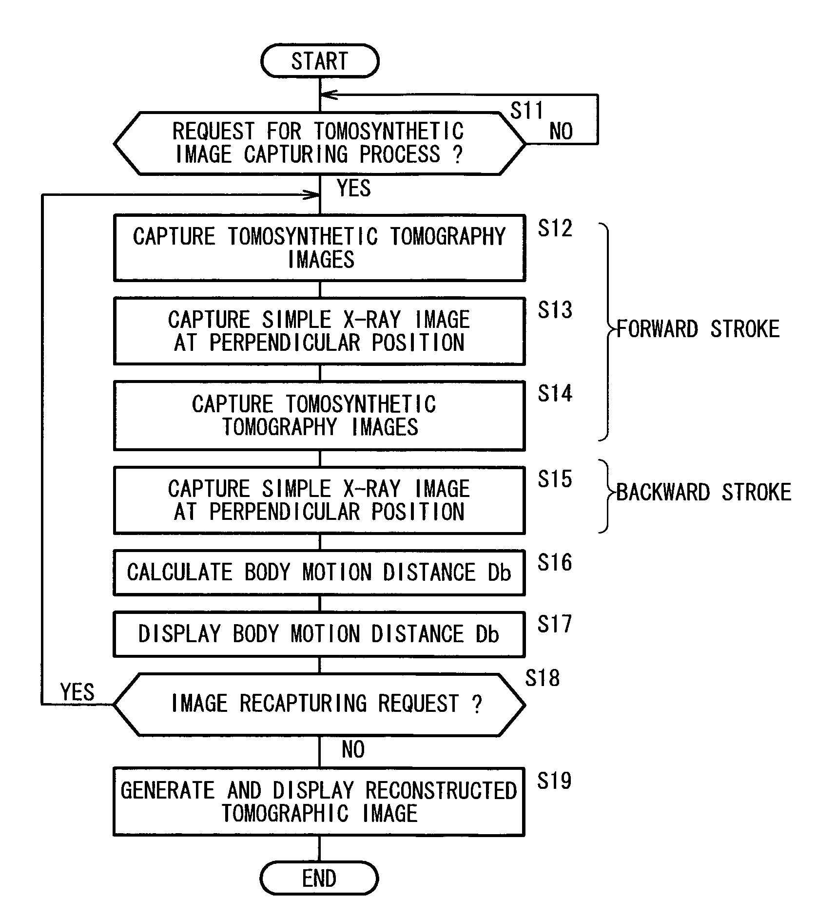
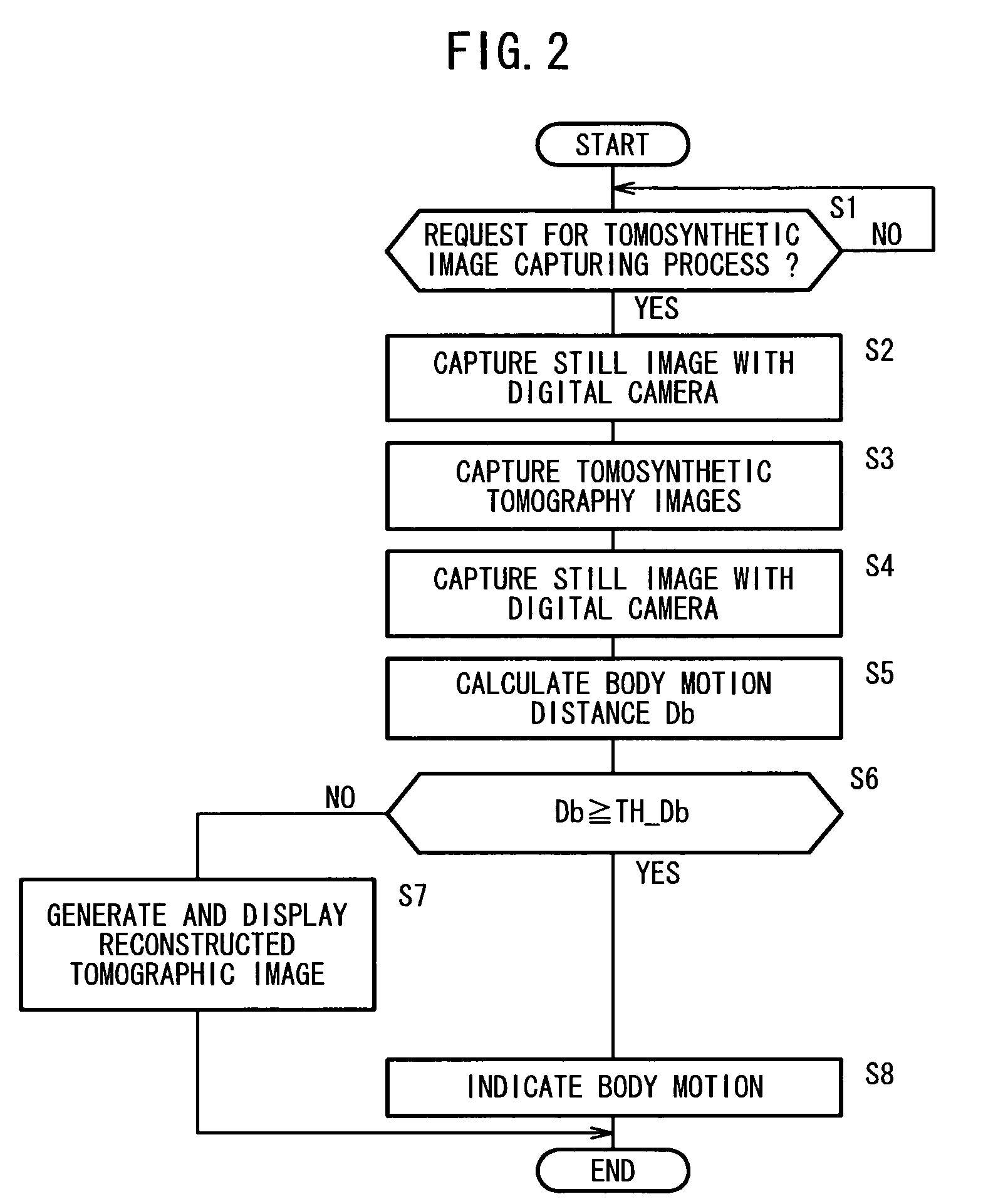
A radiographic tomography apparatus includes a tomosynthetic image capturing section for applying radiation from a radiation source to an examinee at a plurality of different angles, and detecting the radiation transmitted through the examinee with a radiation conversion panel to capture a plurality of tomosynthetic tomography images of the examinee. The radiographic tomography apparatus further includes a still image capturing section for capturing a plurality of still images of the examinee in one image capturing position at different times, and a body motion detector for detecting a body motion of the examinee based on the still images captured by the still image capturing section.

Description

CROSS-REFERENCE TO RELATED APPLICATION[0001]This application is based upon and claims the benefit of priority from Patent Application No. 2008-290761 filed on Nov. 13, 2008, in the Japan Patent Office, of which the contents are incorporated herein by reference.BACKGROUND OF THE INVENTION[0002]1. Field of the Invention[0003]The present invention relates to a radiographic tomography apparatus, which is capable of detecting body motion of an examinee, particularly in cases where the examinee should be kept still while a radiographic image of the examinee is being captured.[0004]2. Description of the Related Art[0005]In a radiographic imaging process, a satisfactory radiographic image of an examinee may not be captured if the body of the examinee moves too much, or if the region of the examinee that is to be imaged significantly changes in position. There have been proposed radiographic tomography apparatus, which are designed to reduce the effect that body motions of the examinee have ...

Claims


Application Information

Patent Timeline
Patent Type & Authority Patents(United States)
IPC IPC(8): G06K9/00
CPCA61B6/025A61B6/527
Inventor NISHIMURA, TOMOYOSHIENOMOTO, JUNSAWADA, HIROFUMIAKAHORI, SADATOKANAGAWA, EIICHIOHTA, YASUNORIIDA, NORIAKI
Owner FUJIFILM CORP
Learn More