
Operating input device for reducing input error

a technology of input error and input device, which is applied in the field of operating input device to achieve the effect of facilitating input operation and preventing input errors

Inactive Publication Date: 2013-01-29
DENSO CORP
View PDF13 Cites 40 Cited by
  • Summary
  • Abstract
  • Description
  • Claims
  • Application Information

AI Technical Summary

Benefits of technology

The patent describes a technology that allows for easier and more accurate touch input on touch panels by using an image of a fingertip. This technology also highlights the position of any manual operation buttons that may be engaged for operation based on the effective finger position. This visual feedback prevents input errors and makes it easier for operators to perform operations. Overall, this technology improves the user experience and makes it easier for operators to use touch panels.

Problems solved by technology

Therefore, even though it is difficult for an operator to perceive the precise point of finger contact on the touch panel, the operator can understand whether a manual operation button or the like is currently positionally engaged for operation based on the effective finger position by way of visual feedback provided by viewing the screen.

Method used


Image

  • Operating input device for reducing input error
  • Operating input device for reducing input error
  • Operating input device for reducing input error

Examples


first embodiment

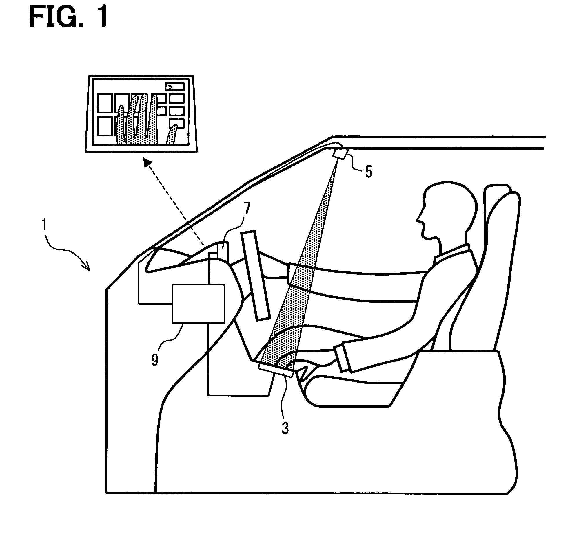
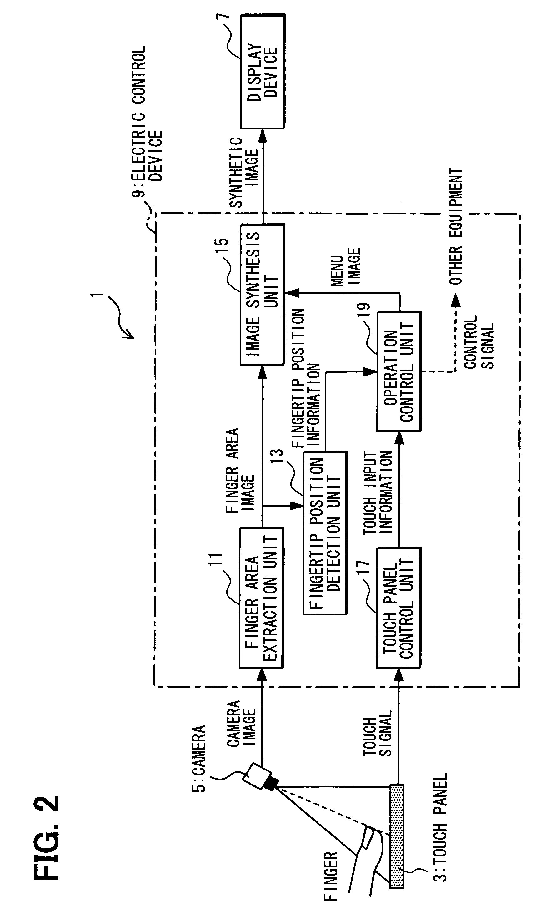
[0061]In accordance with a first exemplary embodiment, for example, as illustrated in FIG. 1 and FIG. 2, the operating input device 1 can be used, for example, as an input device for a car navigation system. The operating input device 1 can include a touch panel 3, a camera 5 such as a video camera for capturing an image of the surface of the touch panel 3 from above, a display device 7 for displaying various objects including interactive objects such as a menu image, menu screen, manual operation buttons and the like, and an electronic control device 9 that can operate as a control unit for controlling the above described elements.

[0062]As illustrated in FIG. 3, X- and Y-coordinates are established in association with the touch panel 3 so that touched areas can be discriminated. X- and Y-coordinates are also established in association with display screen images. For example, a menu screen in which a menu image is displayed on the display device 7 can be associated with certain posi...

second embodiment

[0087]An operating input device in accordance with a second embodiment will be described herein below. It will be understood that description of elements or procedures that are the same as in the first embodiment will be omitted for simplicity.

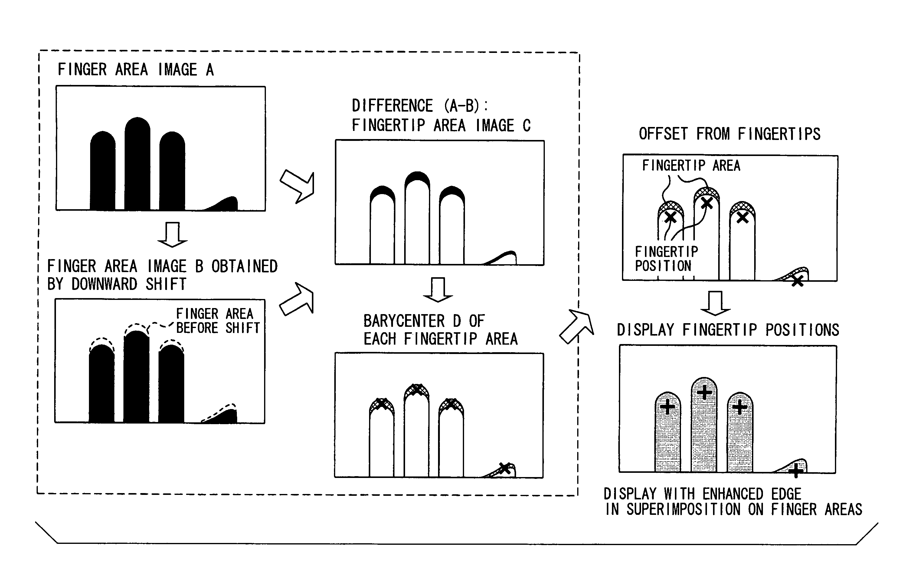
[0088]The present embodiment includes a method for extracting a fingertip area. As illustrated in FIG. 11, a finger area image A is extracted as a binary image from a camera image. The finger area image A is moved or shifted downward toward the base of the fingers to generate a shifted image shown as finger area image B.

[0089]Subsequently, the difference between the finger area image A and the finger area image B, finger area image A-finger area image B, is determined to generate a difference image referred to as fingertip area image C. When a finger is in a position such as inclined and the difference is determined to be negative, the difference value is processed as a zero value.

[0090]The fingertip area image C is contracted to generate a fi...


PUM


Abstract

An operating input device is provided in which input errors can be prevented. A finger area image is extracted from an image captured by a camera. A fingertip area is extracted from a difference image generated between the finger area image and a shifted image. A fingertip position is detected from the fingertip area based on a center of mass. A semitransparent fingertip image is superimposed on the menu image. Manual operation buttons coinciding with fingertip positions are displayed in an emphasized manner. An actual position of a finger press is shifted to coincide with a manual operation button position and the manual operation button is considered to be pressed.

Description

CROSS REFERENCE TO RELATED APPLICATIONS[0001]The present invention is based on and claims priority to Japanese Patent Application No. JP 2007-077330 filed Mar. 23, 2007 the entire contents of which are incorporated herein by reference.BACKGROUND OF THE INVENTION[0002]1. Field of the Invention[0003]The present invention relates to an operating input device for providing input using a touch panel and more specifically to an input device for reducing error.[0004]2. Description of Related Art[0005]Remote controllers are conventionally known for operating in-vehicle units such a car navigation system. However, remote controllers can be difficult to handle while driving. For example, a user is typically required to find a remote controller by fumbling through various portions of the passenger compartment, properly gain a hand hold, and then press the desired button to provide the desired input all without looking away from the road. Various techniques have been proposed to solve the probl...

Claims


Application Information

Patent Timeline
Patent Type & Authority Patents(United States)
IPC IPC(8): G06F3/033
CPCG06F3/0418G06F3/0426
Inventor NAGATA, TAKASHI
Owner DENSO CORP
Learn More