
Formation core sample holder assembly and testing method

a core sample and assembly technology, applied in the direction of suspensions and porous materials analysis, material analysis, instruments, etc., can solve the problems of thermal break down and/or material degradation, inability to maintain the core sample, and provided with elastomeric sleeves, etc., to achieve the effect of not being suitable for exposure to certain chemicals

Inactive Publication Date: 2013-01-22
SHELL OIL CO
View PDF14 Cites 8 Cited by
  • Summary
  • Abstract
  • Description
  • Claims
  • Application Information

AI Technical Summary

Benefits of technology

The invention provides a core sample holder assembly and a method for performing laboratory core flooding experiments with a core sample taken from a hydrocarbon containing formation. The assembly includes a pressure chamber, a flexible core sample holder sleeve, an opening for injecting oil, pressure control means, a fluid injection port, a fluid outlet port, and means for monitoring the migration of injected and / or pore fluid through the pores of the core sample by transmitting electromagnetic radiation through the core via the surrounding hull, oil, and flexible sleete. The technical effects of the invention are improved accuracy and efficiency in the analysis of petroleum reservoirs and performance of laboratory core flooding experiments.

Problems solved by technology

A problem of the known core sample holder assemblies is that they are not suitable to maintain the core sample at elevated temperature and pressure while electromagnetic radiation is transmitted through the core sample to monitor the fluid migration within the core sample.
A further problem of the known core sample holder assemblies is that they are provided with elastomeric sleeves which are not suitable for use at high temperatures of more than 300 degrees Celsius and / or are susceptible to fatigue, thermal break down and / or material degradation.
A further problem of the known core holder assemblies is that they are provided with elastomeric sleeves, which are not suitable to exposure to certain chemicals, such as hydrogen sulphide and carbon dioxide.

Method used


Image

  • Formation core sample holder assembly and testing method
  • Formation core sample holder assembly and testing method

Examples


Embodiment Construction

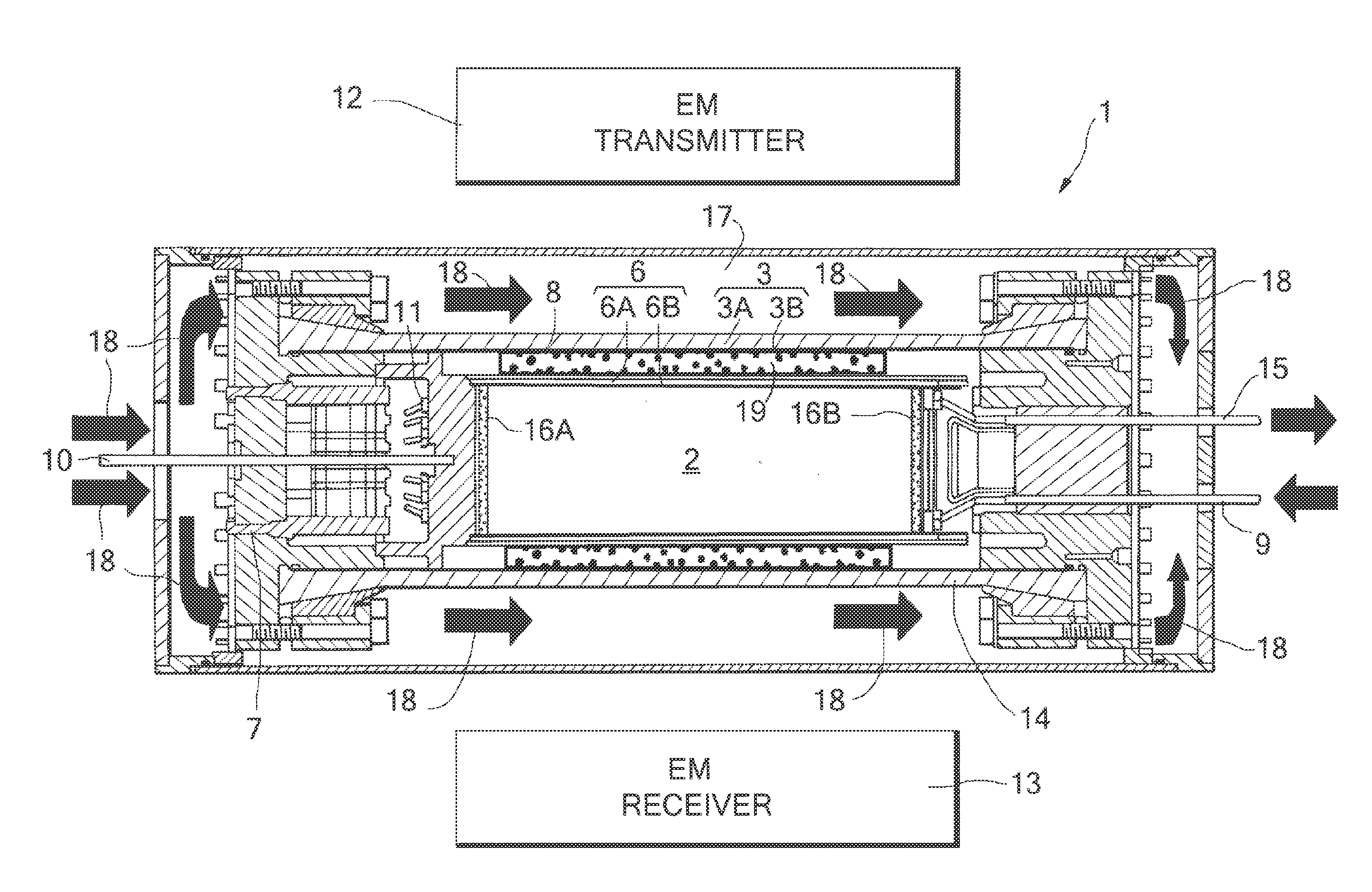
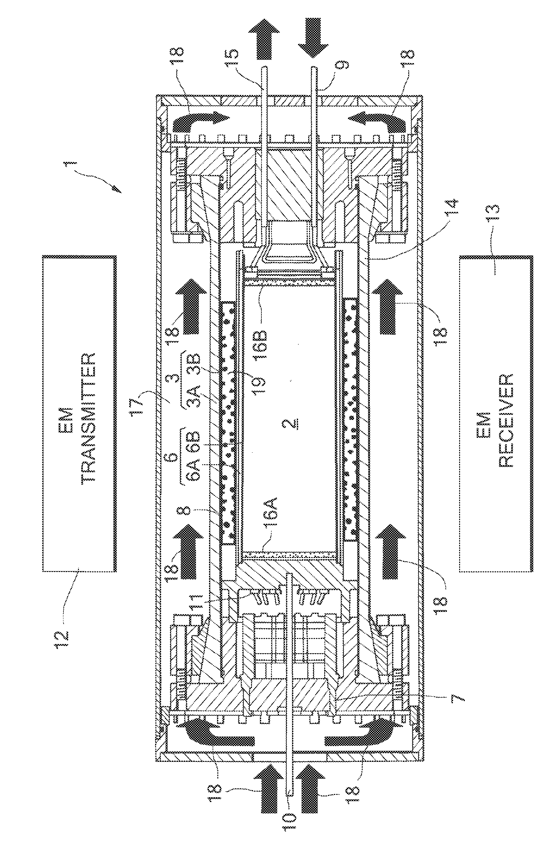
[0030]FIG. 1 depicts a core holder assembly 1 according to the invention in which a cylindrical core sample 2 taken from a hydrocarbon containing formation is tested.

[0031]The core holder assembly 1 comprises:

[0032]a pressure chamber provided by a tubular hull 3, which comprises an outer layer 3A made of a carbon fiber composite material and an inner aluminum liner 3B, and a pair of disk-shaped flanges 4,5 that are arranged at opposite sides of the tubular hull 3;

[0033]a flexible core holder sleeve 6, which is arranged within the tubular hull and is sealingly secured to the disk-shaped flanges and comprises a tubular steel sheet 6A with an inner lining 6B comprising polytetrafluoroethylene (PTFE), which is also known as Teflon (Teflon is a trademark);

[0034]an opening 7 for injecting oil through one of the disk-shaped flanges 5 into an annular space 8 between the tubular hull 3 and the flexible sleeve 6;

[0035]pressure control means for maintaining the oil in the annular space 8 at a ...


PUM

PropertyMeasurementUnit
thickaaaaaaaaaa
boiling temperatureaaaaaaaaaa

Abstract

A core sample holder assembly for performing laboratory core flooding experiments with a core sample:a pressure chamber provided by a tubular hull made of a carbon fiber composite material and an aluminum liner, and a pair of disk-shaped flanges;a flexible core sample holder sleeve within the pressure chamber, which sleeve comprises a tubular steel sheet with a plastic inner lining;an opening for injecting oil into an annular space between the hull and the sleeve;pressure control means for maintaining the oil at a predetermined pressure;an fluid injection port for injecting a fluid into a cylindrical core sample within the sleeve;a fluid outlet port arranged in the other flange for discharge of fluid from the core sample; andmeans for monitoring the migration of injected and / or pore fluid through the pores of the core sample.

Description

PRIORITY CLAIM[0001]The present application claims priority of PCT Application EP2008 / 055003, filed 24 Apr. 2008, which claims priority to European Patent Application No. 07107024.7 filed 26 Apr. 2007.BACKGROUND OF THE INVENTION[0002]The invention relates to a formation core sample holder assembly and a core testing method. In the oil and gas production industry it is common practice to take, when an exploration or production well is being drilled, one or more cylindrical core samples of hydrocarbon containing or other formation and to subsequently perform one or more tests with this core sample in a laboratory.[0003]During these tests the sample is arranged in a pressurized sample holder assembly, in which the temperature and pressure are substantially similar to the ambient pressure and temperature within the hydrocarbon containing or other formation from which the sample has been taken, and a treating, completion and / or stimulation fluid is injected into the sample to determine a...

Claims


Application Information

Patent Timeline
Patent Type & Authority Patents(United States)
IPC IPC(8): G01N15/08
CPCG01N15/0806G01N33/241G01N15/08G01N33/24
Inventor COENEN, JOSEPH GUILLAUME CHRISTOFFEL
Owner SHELL OIL CO
Learn More