Eureka AIR delivers breakthrough ideas for toughest innovation challenges, trusted by R&D personnel around the world.

Floor span connector

a technology of floor spans and connectors, applied in the field of construction industry, can solve the problems of manifold disadvantages of coil straps, increase production costs, and damage to the structure, and achieve the effects of less material, limited adjustability, and increased economic benefits

Active Publication Date: 2013-01-22
SIMPSON STRONG TIE
View PDF66 Cites 5 Cited by
  • Summary
  • Abstract
  • Description
  • Claims
  • Application Information

AI Technical Summary

Benefits of technology

[0007]The present invention provides a single-piece connector that uses less material, and is therefore more economical to produce, than connectors in the prior art. In particular the diagonally-slanted support leg, preferably reinforced with shallow walls on either side, eliminates the need for an additional member to support or reinforce the seat member.
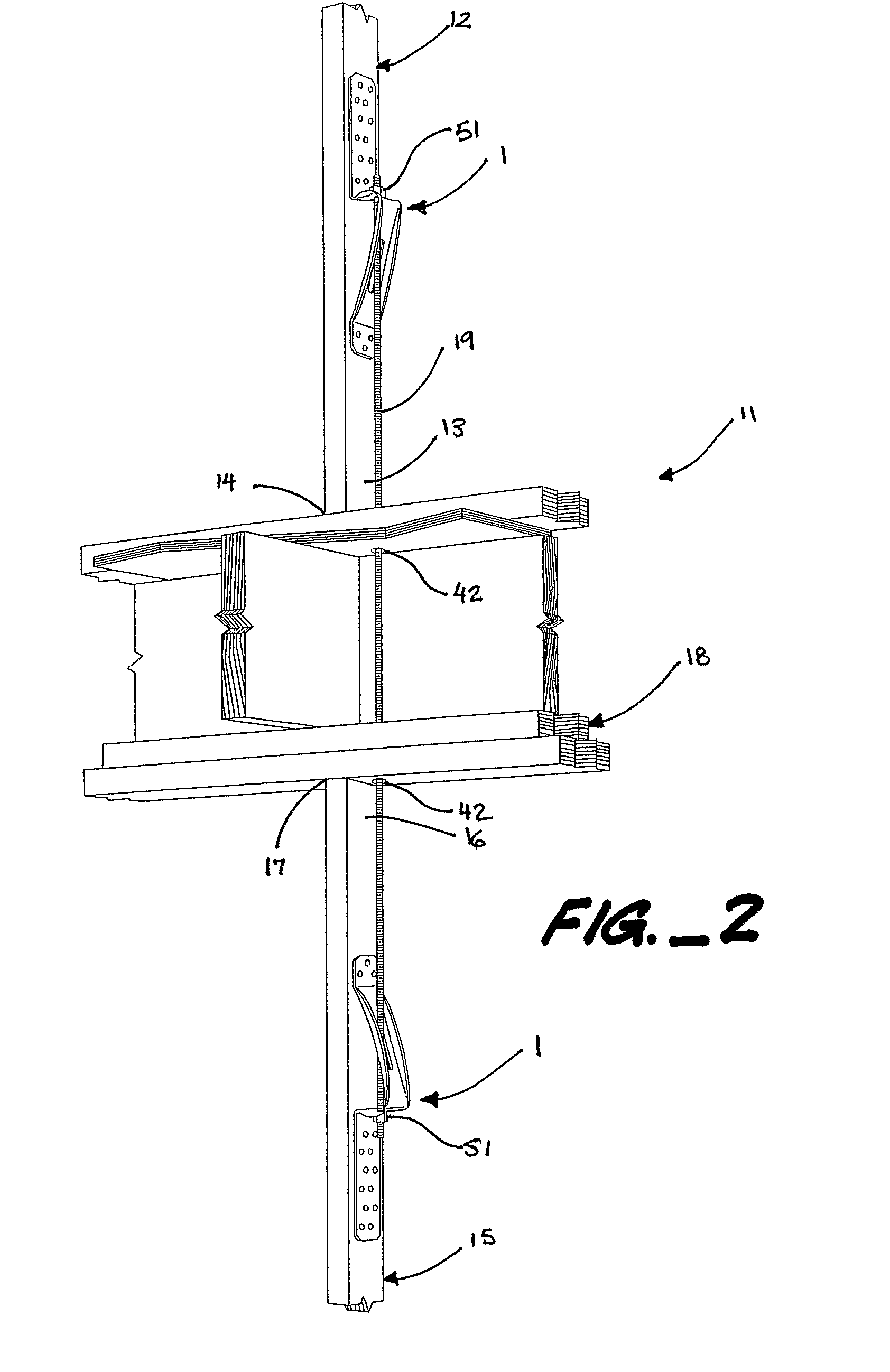
[0008]The present invention provides a connector that can be used, and a connection that can be made, inside the walls of the structure, thereby eliminating the exposure of coil strap, as in the prior art, which must be attached to the outer faces of the wall studs.
[0009]The present invention provides a connector with obround openings that permit limited adjustability and ease installation in narrow wall cavities.
[0010]The present invention provides a connection that is easy to install because it uses standard all thread rod, which is easily procured and can be easily run through a hole or holes drilled in the sill plates of the floor structure between the connected wall studs.

Problems solved by technology

If these forces exceed the structural capacity of the building, they can cause structural failures leading to anything from minor damage to catastrophic destruction of the building, attendant economic loss, and injuries or fatalities.
The disadvantages of coil strap are manifold.
Coil strap cannot be installed within a wall because of the intervening sill plates.
Coil strap cannot accommodate any offset in the upper and lower studs.
Wood shrinkage after strap installation across horizontal wood members can cause the strap to buckle outward.
Vertically-paired holdowns can eliminate some of the disadvantages of the coil strap, but holdowns are typically engineered for higher load values that are necessary in a floor-to-floor connection and therefore waste material and increase costs.

Method used


Image

  • Floor span connector
  • Floor span connector
  • Floor span connector

Examples


Embodiment Construction

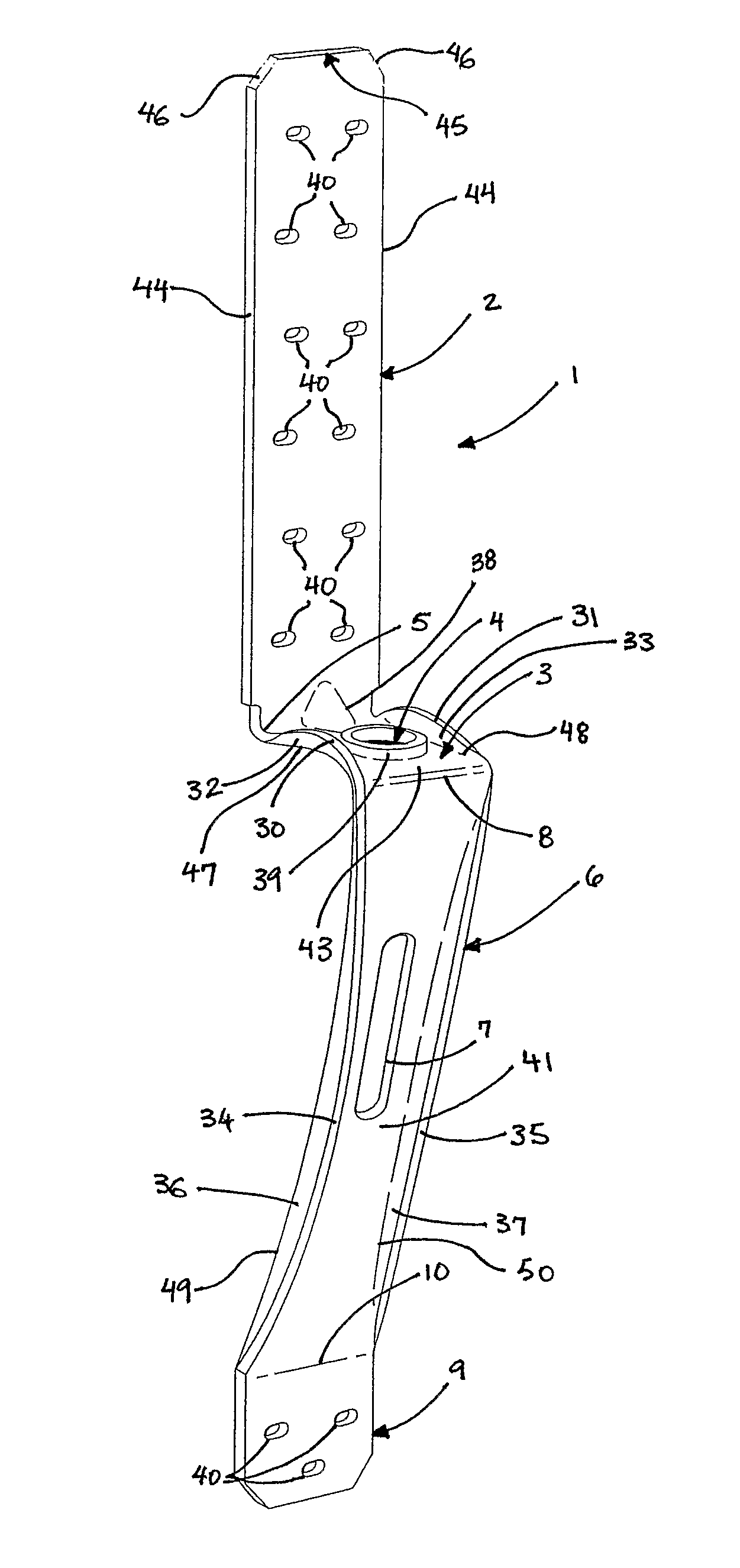
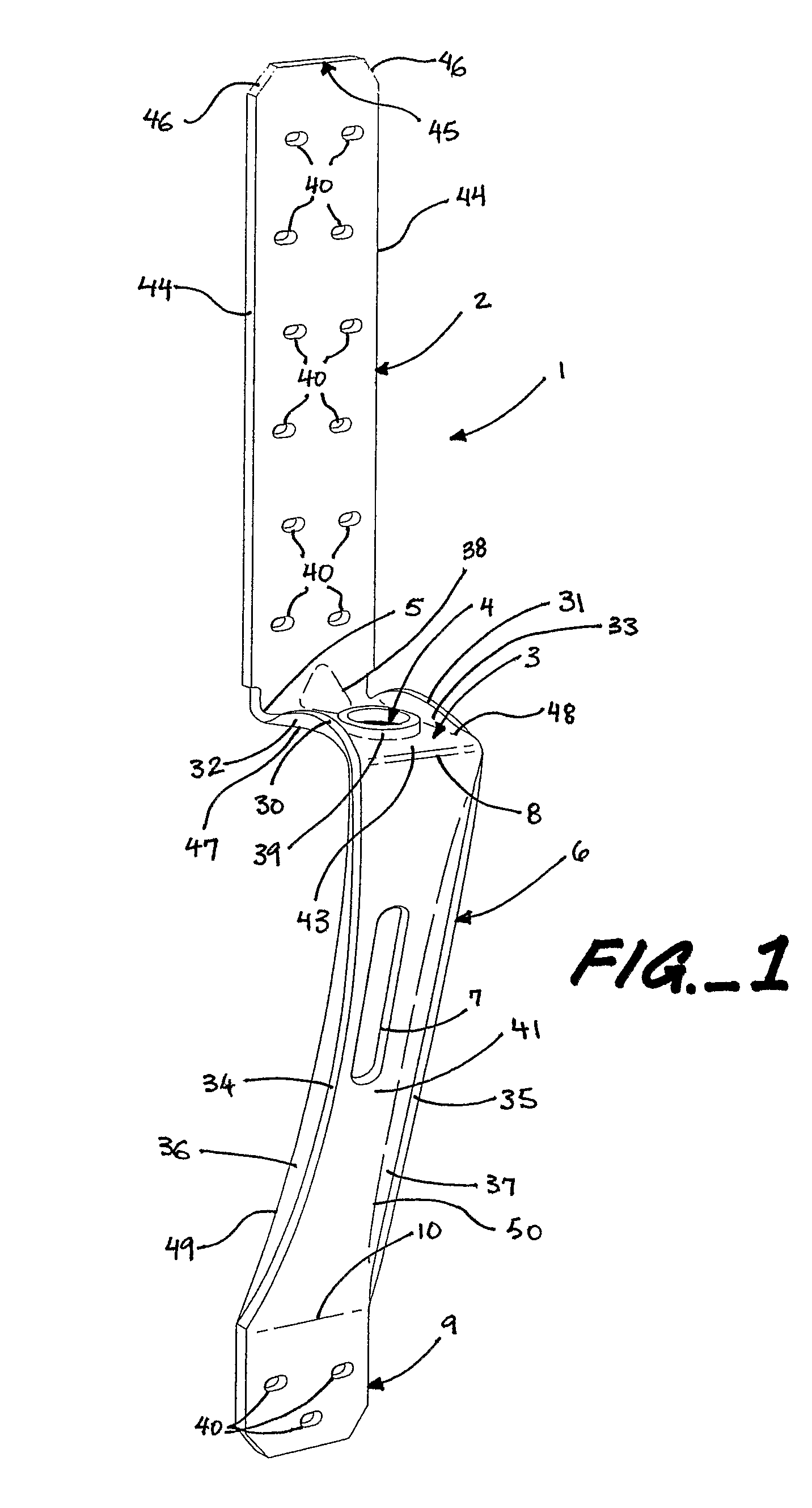
[0016]The connector 1 of the present invention is preferably formed out of galvanized sheet steel using automated machinery. The connector 1 is preferably formed by cutting, punching and bending the sheet steel. However, the connector 1 can be formed by any appropriate method and material, for instance by casting metals such as aluminum and molding plastics.

[0017]At its most basic, the connector 1 of the present invention comprises a first substantially planar attachment tab 2, a first substantially planar seat member 3, a first substantially planar support leg 6, and a second substantially planar attachment tab 9.

[0018]Preferably, the first attachment tab 2 has an attachment face 20 and an opposite outer face 21. Preferably, the first attachment tab 2 is elongated, with two relatively long and parallel side edges 44 and a relatively short end edge 45 that connects the two side edges 44. The end edge 45 preferably has two diagonal end portions 46 that cut off what would otherwise be...


PUM


Abstract

A connector for connecting wall studs of two adjacent floors in a light frame building structure, the connector having a first attachment tab, a seat member, a diagonally slanted support leg, and a second attachment tab, all substantially planar. The connector is intended to be paired and the paired connectors joined by an elongated tie member that pierces the sill plates of the intervening floor structure.

Description

BACKGROUND OF THE INVENTION[0001]1. Field of the Invention[0002]The present invention relates to the construction industry and, in particular, concerns a method of interconnecting building members with paired connectors and tie rods.[0003]2. Description of the Related Art[0004]In typical residential and light industrial and commercial building frame wall construction, load bearing frame walls comprise a series of studs and posts that are anchored to the foundation and covered with sheathing material installed over both sides of the frame. Typically, the frame is constructed from a number of vertically extending studs that are positioned between and connected to horizontally extending top and bottom plates. The bottom plate and the vertical studs are typically anchored to the foundation by some means. The sheathing material, which can be plywood, gypsum wallboard, siding, plaster, or the like, is then attached over the studs.[0005]Natural forces commonly impose vertical and horizonta...

Claims


Application Information

Patent Timeline
Patent Type & Authority Patents(United States)
IPC IPC(8): E02D5/74E02D5/70
CPCE04B1/2604E04B2001/3583
Inventor LIN, JIN-JIE
Owner SIMPSON STRONG TIE
Why Eureka
Eureka Blog
Learn More