
Active matrix liquid crystal device

a liquid crystal device and active matrix technology, applied in static indicating devices, non-linear optics, instruments, etc., can solve the problems of loss of contrast ratio, undesirable system based on heating element methods, degraded image quality of display devices using liquid crystal (lc) and other problems, to achieve the effect of reducing contrast ratio, accurate measurement of liquid crystal material temperature, and reducing loss of display quality

Inactive Publication Date: 2013-01-15
SHARP KK
View PDF21 Cites 9 Cited by
  • Summary
  • Abstract
  • Description
  • Claims
  • Application Information

AI Technical Summary

Benefits of technology

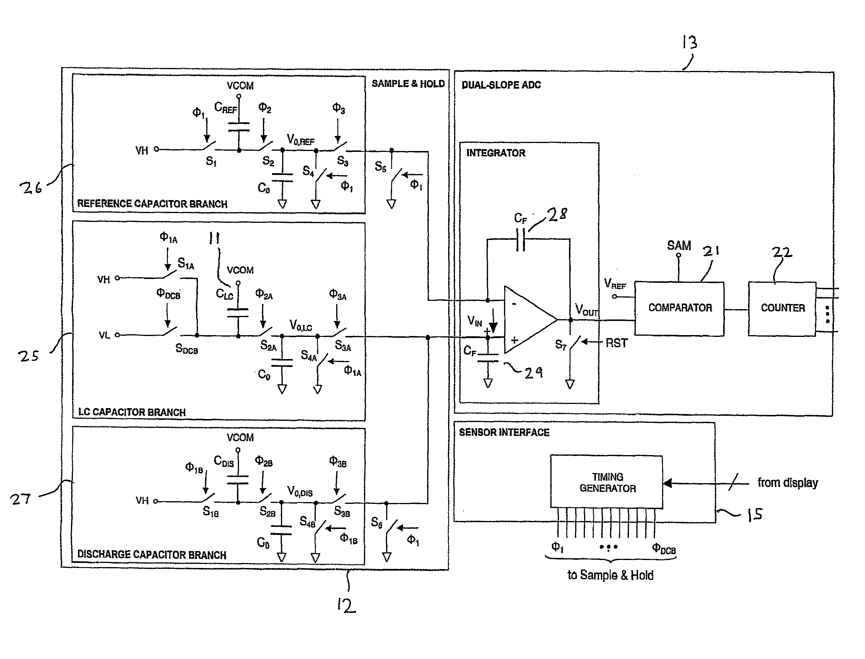
[0012]It is thus possible to provide an arrangement which automatically calibrates an AMLCD for errors, for example introduced by manufacturing tolerances. Such an arrangement also provides compensation, for example, for non-idealities such as charge-injection from transistor switches within the device. No additional connections are required and no external calibration steps are needed. Such an arrangement is therefore capable of providing a more accurate measure of the capacitance of a temperature sensing capacitor with the liquid crystal layer of the device forming the dielectric, and hence of the temperature of the liquid crystal material of the layer.
[0022]The resulting measure may be used to compensate for the effects of temperature, for example in the case of a liquid crystal display. Where such displays are used in environments with substantially varying temperatures, compensation can be provided so as to reduce any loss in display quality such as reduction in contrast ratio. It is possible for all of the circuitry associated with measuring the capacitance to be formed within the device so that no additional connections between the device and other components are required. This arrangement may be incorporated with no modification to the design or operation of, for example, device driver circuits or the pixel matrix. A relatively accurate measure of the liquid crystal material temperature may therefore be obtained and may be used to provide high quality compensation for temperature variations in the display performance.

Problems solved by technology

Display devices utilising liquid crystal (LC) have historically suffered degraded image quality through loss of contrast ratio as a result of temperature-induced changes in the optical properties of the liquid crystal material.
In general, systems based on the heating element method are undesirable compared to the driving voltage compensation method due to the increased power consumption associated with the heating element.
Disadvantages of this method include: indirect measurement of the liquid crystal temperature (it is the temperature of the glass, or substrate on which the detection element is mounted, that is actually being measured and not the LC); extra connections to the display reducing reliability; and extra components and fabrication steps raising the cost.
Thus the device still has the disadvantages of performing indirect measurement of temperature and requiring extra connections to the display.
An additional disadvantage is that the process variation typical of elements integrated onto the display substrate limits the accuracy of such systems.
Whilst this is suitable for on / off control of a heating element, as in a control loop, disadvantageously the system does not supply a measure of absolute temperature as would be required in a preferred driving voltage compensation system.
This is difficult to achieve in practice requiring a significant increase in complexity of the display driving circuits;it is difficult to accurately define capacitor values, including the liquid crystal capacitor element, in practice.

Method used


Image

  • Active matrix liquid crystal device
  • Active matrix liquid crystal device
  • Active matrix liquid crystal device

Examples


Embodiment Construction

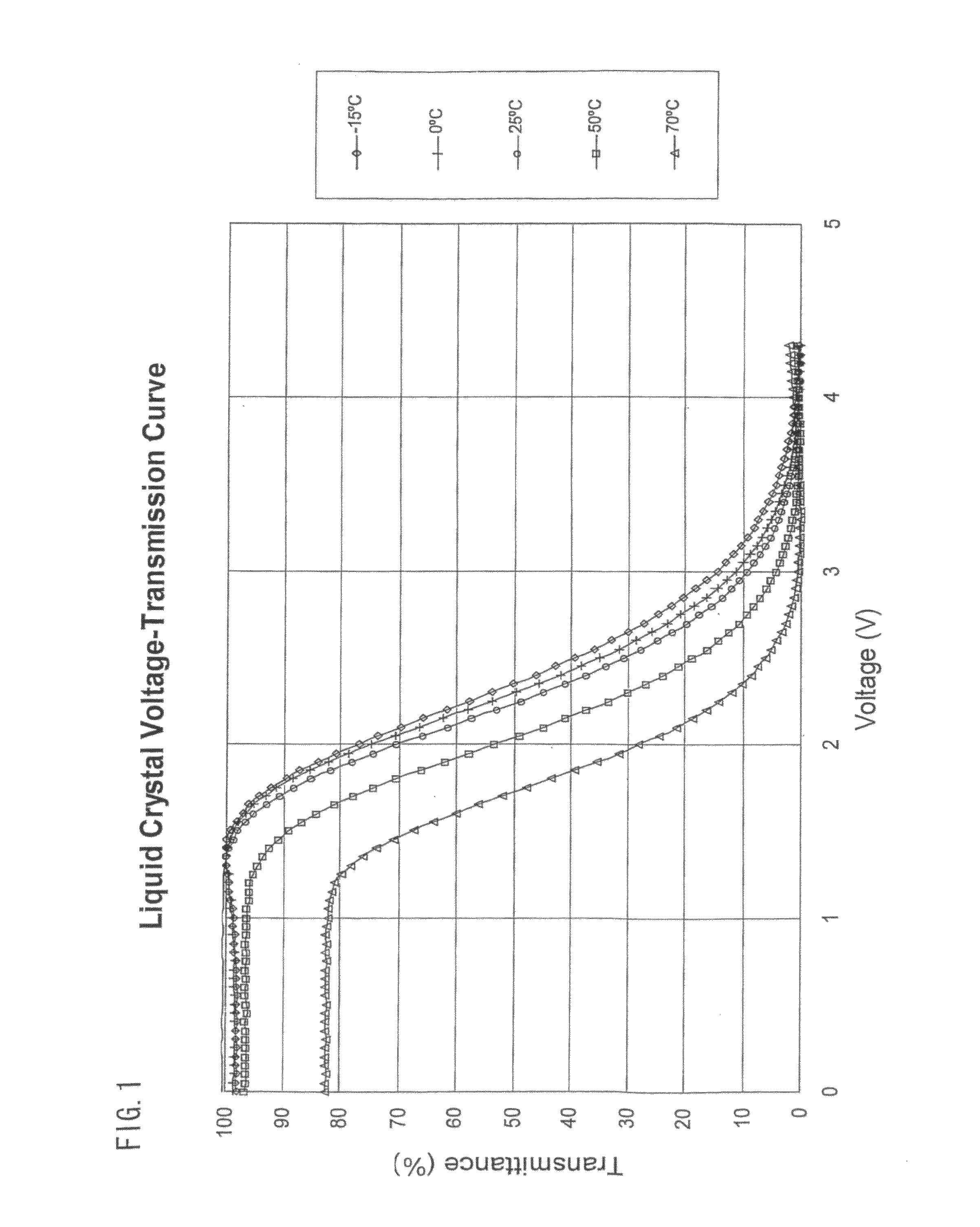
[0047]As mentioned hereinbefore, the performance of an active matrix liquid crystal device (AMLCD), such as the display performance of a display, varies with the temperature of the liquid crystal material of the device. FIG. 1 illustrates how the transfer function between pixel drive voltage and pixel transmittance varies for a range of temperatures to which such a device may be subjected during operation. For example, such devices may be used to provide displays in vehicles and may be subjected to a very wide range of temperatures. In order to reduce the effects of temperature variations on display performance, compensation has to be provided.

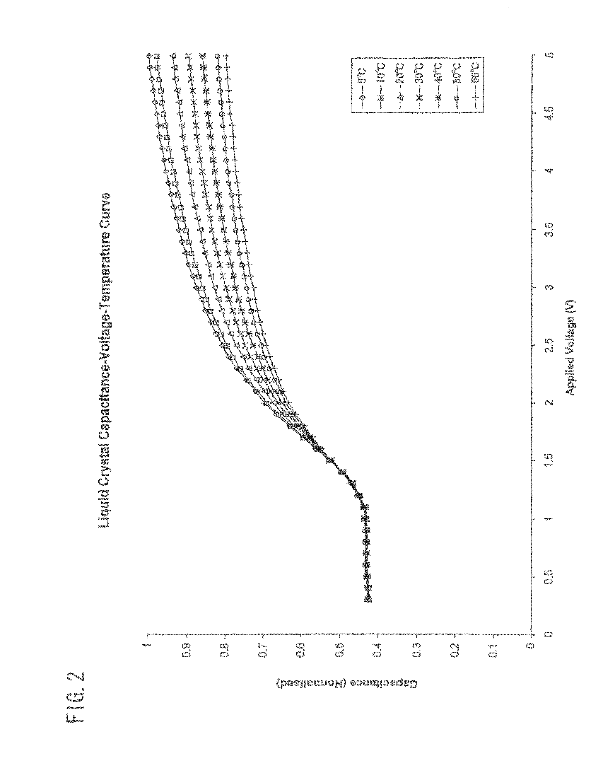
[0048]As mentioned hereinbefore, the capacitance of a liquid crystal capacitor whose dielectric is formed by the liquid crystal material of the device may be used to provide a measure of the actual temperature of the liquid crystal material and this measure may be used in an arrangement for providing temperature compensation. However, the capa...


PUM


Abstract

In one embodiment of the present invention, an active matrix liquid crystal device includes an active matrix substrate and a counter electrode substrate separated by a layer of liquid crystal material. A temperature sensing capacitor includes electrodes on the substrates separated by the liquid crystal layer, which thus forms the dielectric of the capacitor. A reference capacitor and a calibration capacitor are also provided and have nominally the same capacitance. These capacitors form part of charge-transfer capacitance measuring branches within a sample / hold circuit. During a calibration cycle, the sample / hold circuit provides a signal dependent on the difference between the capacitances of the calibration capacitor and the reference capacitor and this is supplied to an analog / digital converter, which forms a reference voltage. During subsequent parts of the measurement cycle, the converter converts the output of the sample / hold circuit using the reference voltage in order to improve the accuracy of measurement of the liquid crystal capacitor, and hence the temperature of the liquid crystal material. This temperature measurement may be used, for example, to compensate the AMLCD for the effects of temperature variation in the liquid crystal properties.

Description

TECHNICAL FIELD[0001]The present invention relates to an active matrix liquid crystal device (AMLCD).BACKGROUND ART[0002]Display devices utilising liquid crystal (LC) have historically suffered degraded image quality through loss of contrast ratio as a result of temperature-induced changes in the optical properties of the liquid crystal material. In particular, the voltage-transmission curve of a liquid crystal is related to its temperature, as shown in FIG. 1 of the accompanying drawings.[0003]A well-known solution for this degradation in image quality is to provide a temperature controlled contrast ratio compensation system comprising means for measuring the temperature of the display and means for altering the voltages applied to the display based on this measurement. Such a system is disclosed for a segmented liquid crystal display in EP0012479 and for an AMLCD in U.S. Pat. No. 5,926,162.[0004]Alternatively, a temperature control system may be provided comprising means for measu...

Claims


Application Information

Patent Timeline
Patent Type & Authority Patents(United States)
IPC IPC(8): G09G3/36
CPCG09G3/3648G09G3/3614G09G2320/041G02F1/136213G09G3/3625G02F1/136204
Inventor BROWN, CHRISTOPHER J.
Owner SHARP KK
Learn More