
Method and apparatus for elevating a marine platform

a technology for marine platforms and equipment, applied in the field of marine platforms, can solve the problems of marine platform equipment located on the deck of the marine platform being easily damaged, marine platform collapse, etc., and achieve the effects of more freeboard, more protection, and more clearan

Active Publication Date: 2013-01-15
VERSABAR
View PDF14 Cites 12 Cited by
  • Summary
  • Abstract
  • Description
  • Claims
  • Application Information

AI Technical Summary

Benefits of technology

The present invention solves problems and shortcomings by raising the deck of an existing marine platform, giving more space between the deck and the water surface. This provides better protection for equipment on the deck during severe weather like hurr27,29,30s,32.

Problems solved by technology

When storms strike over a body of water, offshore marine platforms are put at risk.
While the jacket and platform are typically designed to resist hurricane force wind and wave action, equipment located on the deck of the marine platform can easily be damaged if hurricane generated wave action reaches the deck area.
An additional consequence of wave action reaching the platform deck is catastrophic platform collapse, which happened in several instances during recent storms (e.g., hurricane Katrina in the United States Gulf of Mexico).

Method used


Image

  • Method and apparatus for elevating a marine platform
  • Method and apparatus for elevating a marine platform
  • Method and apparatus for elevating a marine platform

Examples


Embodiment Construction

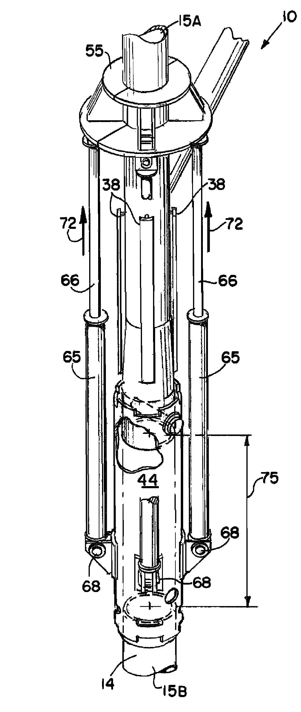
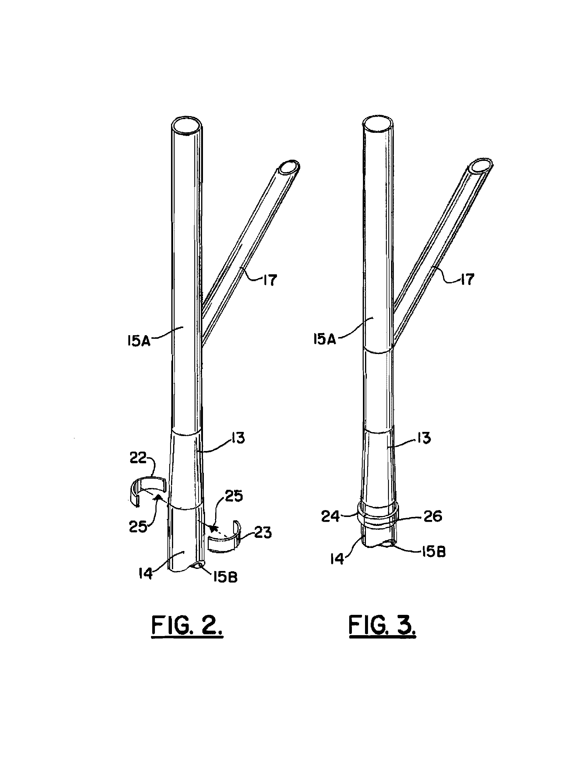
[0055]The present invention provides a marine platform deck elevating system 10 that is shown generally in FIGS. 14-15 and 17 and in method steps that are illustrated in FIGS. 2-18.

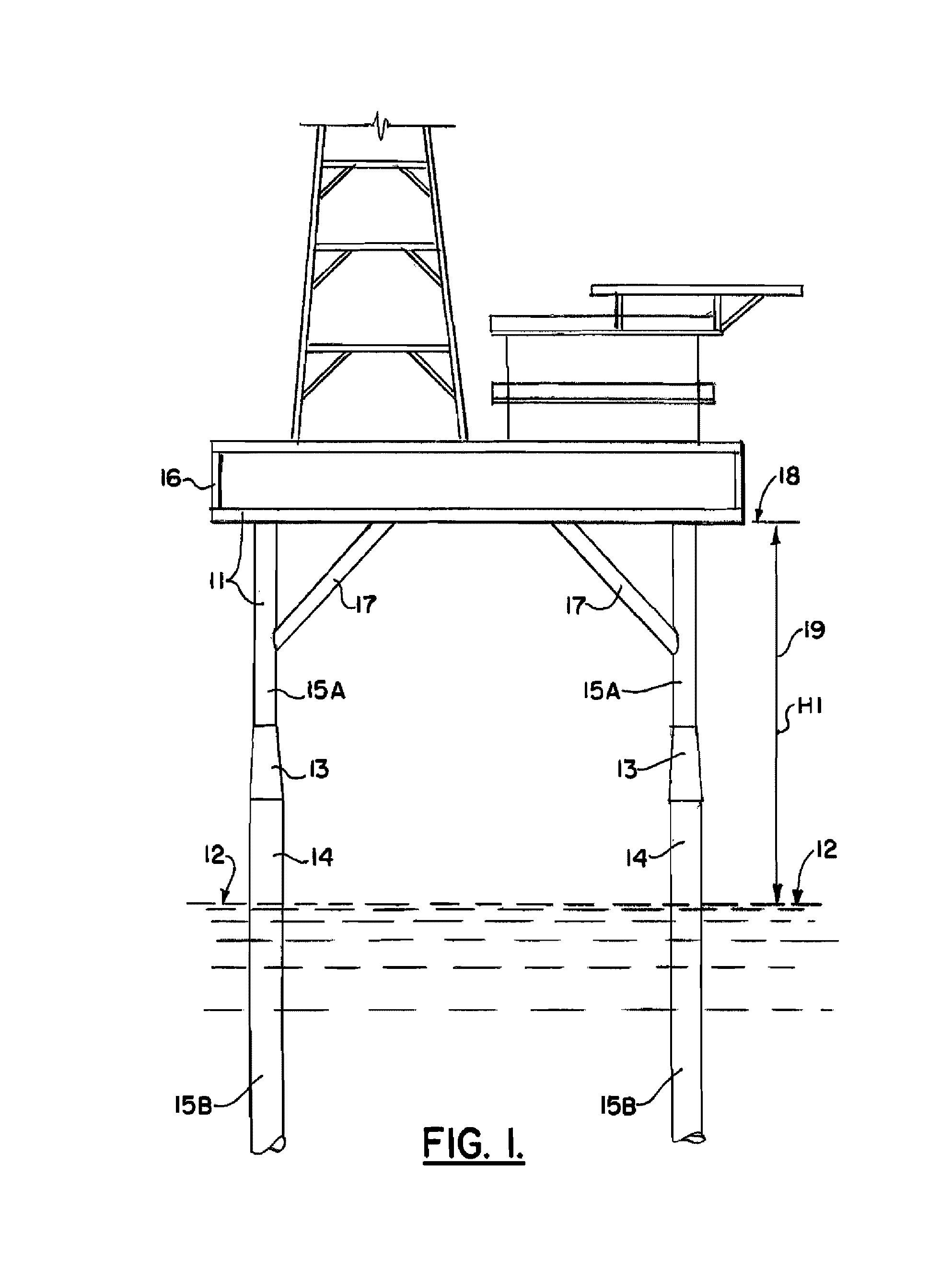
[0056]In FIG. 1, a fixed marine platform 11 is shown having a deck 16 that is positioned at an elevation 18 that is elevated above the water surface 12 a distance H1 that is indicated by the numeral 19 in FIG. 1. The numeral 19 and the dimension line H1 represent the existing clearance above water. It is necessary to protect equipment that is contained on the deck 16 from storm generated wave action. Storms such as hurricanes can generate a storm surge and wave action that puts equipment and / or personnel located on deck 16 at peril. If a deck is not located at a safe elevation, it must be elevated.

[0057]FIG. 1 illustrates a typical fixed platform 11 having a plurality of legs 14 that support the deck 16. Diagonal braces 17 can extend between legs 14 and deck 16 as shown in FIG. 1. The platform 11 can incl...


PUM


Abstract

A method of elevating the deck area of a marine platform (e.g., oil and gas well drilling or production platform) utilizes a specially configured sleeve support to support the platform legs so that they can be cut. Once cut, rams or jacks elevate the platform above the cuts. The sleeve support is then connected (e.g., welded) to the platform leg and becomes part of the structural support for the platform. In one embodiment, two sleeves are employed. In another embodiment, the jacks or rams elevate in two stages including a first stage wherein one sleeve elevates and the other sleeve does not elevate and a second stage wherein both sleeves elevate together.

Description

CROSS-REFERENCE TO RELATED APPLICATIONS[0001]This is a continuation in part of U.S. patent application Ser. No. 11 / 749,587, filed 16 May 2007 (issuing as U.S. Pat. No. 7,780,375 on 24 Aug. 2010), which is a nonprovisional of U.S. Provisional Patent Application Ser. No. 60 / 824,005, filed 30 Aug. 2006, each of which are hereby incorporated herein by reference, and priority of each is hereby claimed.[0002]Priority of U.S. Provisional Patent Application Ser. No. 61 / 356,813, filed 21 Jun. 2010, incorporated herein by reference, is hereby claimed[0003]U.S. patent application Ser. No. 12 / 813,290, filed 10 Jun. 2010 (issued as U.S. Pat. No. 8,002,500 on Aug. 23, 2011), is hereby incorporated herein by reference.STATEMENT REGARDING FEDERALLY SPONSORED RESEARCH OR DEVELOPMENT[0004]Not applicableREFERENCE TO A “MICROFICHE APPENDIX”[0005]Not applicableBACKGROUND OF THE INVENTION[0006]1. Field of the Invention[0007]The present invention relates to marine platforms such as oil and gas well drilli...

Claims


Application Information

Patent Timeline
Patent Type & Authority Patents(United States)
IPC IPC(8): E02B17/08
CPCE02B17/0809E02B17/027E02B17/0034E02B17/021E02B2017/0056E02B2017/0073E02B2017/0095
Inventor KHACHATURIAN, JONGREEVES, E. JOHN
Owner VERSABAR
Learn More