
Method and apparatus for adjusting and testing an image sensor module

a technology of image sensor module and automatic adjustment, which is applied in the direction of optical apparatus testing, instruments, optical axis determination, etc., can solve the problems of inability to correct or compensate mechanism errors, affect the consistency of focusing quality of image sensor module, and affect the position of lens, so as to facilitate and precisely adjust the focus of image sensor module. , the effect of engaging with the lens

Inactive Publication Date: 2013-01-08
CHENG UEI PRECISION IND CO LTD
View PDF1 Cites 2 Cited by
  • Summary
  • Abstract
  • Description
  • Claims
  • Application Information

AI Technical Summary

Benefits of technology

The present invention provides a method and apparatus for automatically adjusting and testing an image sensor module. This allows for compensation of mechanism errors that may occur during mounting of the image sensor module to facilitate automatic focusing. The method and apparatus can conveniently and accurately adjust the focus of the image sensor module, providing improved efficiency and accuracy in image capture.

Problems solved by technology

Because the manual adjusting and testing operation is varied with the different operators and the result thereof is depending on individual judgments, this manual operation inevitably can affect the consistency of the focusing quality of the image sensor module.
Whereas, mechanism errors produced in the mounting process of the image sensor module, can affect the position of the lens relative to a standard reference position specified on the lens barrel.
The second mode cannot correct or compensate the mechanism errors before focusing, so it is not convenience for the focusing device to make the focusing wheel mechanism engage with the lens.
When the mechanism errors exceed a permitted limit, it is resulted that the focusing device cannot automatically adjust lens.

Method used


Image

  • Method and apparatus for adjusting and testing an image sensor module
  • Method and apparatus for adjusting and testing an image sensor module
  • Method and apparatus for adjusting and testing an image sensor module

Examples


Embodiment Construction

[0015]The following embodiment with reference to the accompanying drawings now has been given for detail describing the technology, the feature, the object and the effect of the present invention.

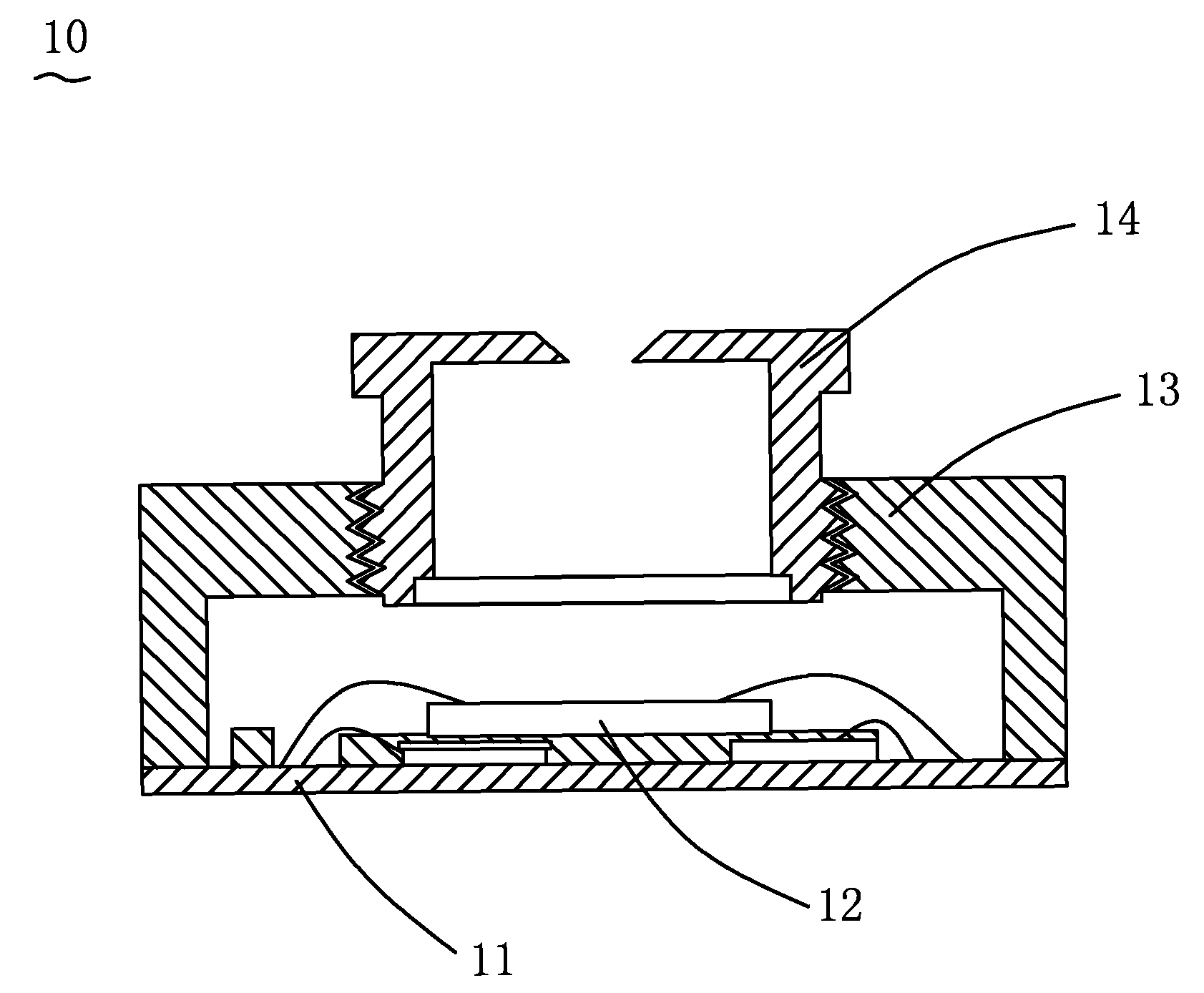
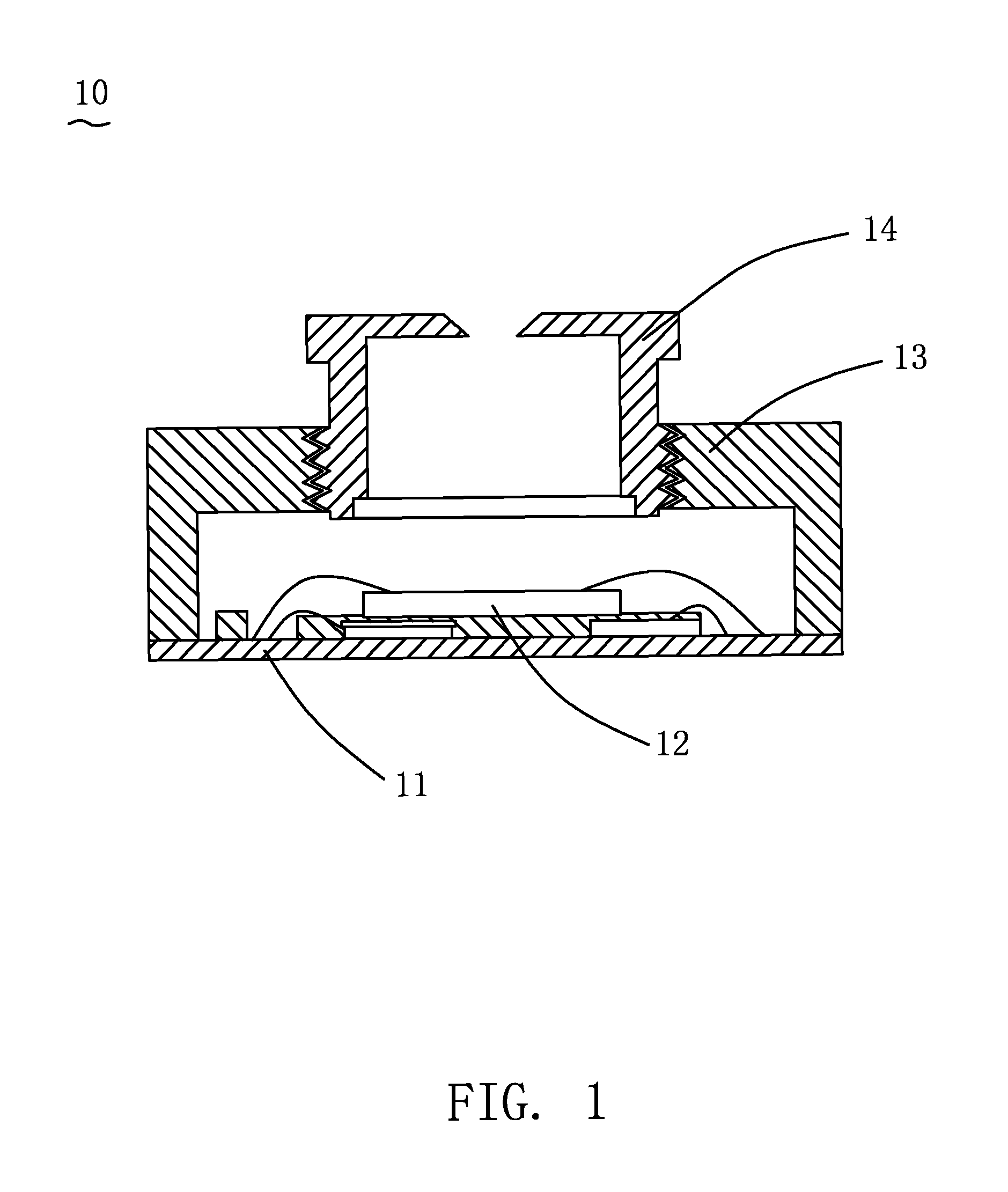
[0016]Please refer to FIG. 1, an image sensor module 10 includes a circuit board 11, an image sensor 12 mounted on a center position of the circuit board 11, a lens barrel 13 fixed on the circuit board 11, and a lens 14 mounted in the lens barrel 13 and located above the image sensor 12.

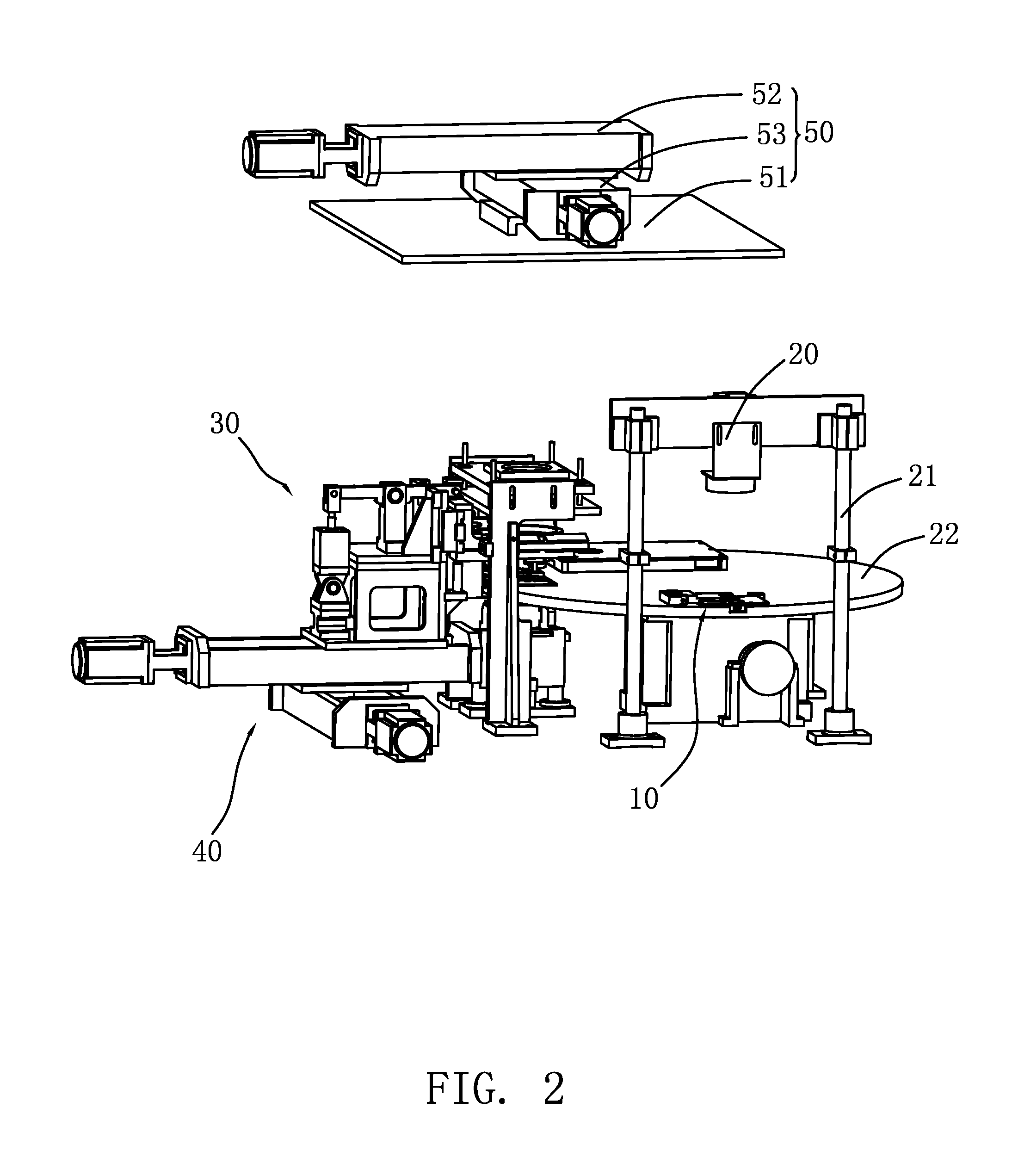
[0017]Referring to FIG. 2, an apparatus for adjusting and testing the image sensor module 10, comprises a video camera 20, a supporting bracket 21 used to fix the video camera 20, a transferring mechanism 22, a focusing mechanism 30, a stepper motor component 40 controlling the focusing mechanism 30, and a controller (not shown in all FIGS). The supporting bracket 21 is located on one side of the periphery of the transferring mechanism 22, and the focusing mechanism 30 is located on the other side of the per...


PUM


Abstract

A method for adjusting and testing an image sensor module is provided. The method of the present invention includes steps of: (1) calculating longitudinal and transverse deviation values of a center point of a lens relative to a standard reference position specified on a lens barrel, and an angle deviation value of the lens according to position signals of the lens on the image sensor module; (2) compensating the longitudinal and transverse deviation values of the center point of the lens, and the angle deviation value of the lens for exactly positioning the lens; and (3) adjusting focus of the image sensor module. The method of the present invention can compensate the mechanism errors produced in the mounting process of the image sensor module for conveniently and exactly adjusting the focus of the image sensor module. An apparatus for adjusting and testing an image sensor module is also provided.

Description

BACKGROUND OF THE INVENTION[0001]1. Field of the Invention[0002]The present invention relates to a method for adjusting and testing, and more particularly to a method and apparatus for automatically adjusting and testing an image sensor module.[0003]2. Description of the Prior Art[0004]At present, an image sensor module mainly includes a circuit board, an image sensor mounted on a center position of the circuit board, a lens barrel fixed to the circuit board, and a lens mounted in the lens barrel and located above the image sensor. During the mounting process of the image sensor module, after the lens is mounted in the lens barrel, it is needed to focus the lens, namely to adjust the distance between the lens and the image sensor. Prior methods for adjusting the lens mainly have two modes. A first mode is adopting manual operation for focusing. Because the manual adjusting and testing operation is varied with the different operators and the result thereof is depending on individual ...

Claims


Application Information

Patent Timeline
Patent Type & Authority Patents(United States)
IPC IPC(8): G02B7/04G01B7/00
CPCG01M11/0207G01M11/0221G01M11/0228
Inventor WANG, HAN-WEISHEN, TSAI-SHENGLIU, JUNG-KUANG
Owner CHENG UEI PRECISION IND CO LTD
Learn More