
Method for material removal and device for carrying out said method

a material removal and material technology, applied in the direction of laser beam welding apparatus, welding apparatus, metal-working apparatus, etc., can solve the problems of unfavorable material removal, unfavorable material removal, and unfavorable material removal, so as to avoid unnecessarily small incident angles, reduce the effect of beam radius and greater raleigh length

Active Publication Date: 2013-01-08
FRAUNHOFER GESELLSCHAFT ZUR FOERDERUNG DER ANGEWANDTEN FORSCHUNG EV
View PDF23 Cites 4 Cited by
  • Summary
  • Abstract
  • Description
  • Claims
  • Application Information

AI Technical Summary

Benefits of technology

The patent text describes a method to reduce vibrations caused by removing material from a workpiece. One way to do this is to adjust the angle at which particles are incident on the surface of the workpiece. By keeping the angle below a certain threshold, the method reduces the amplitude of vibrations. Additionally, the text suggests setting the position of the beam axis in a way that helps to decrease these vibrations. Overall, this method helps to improve the accuracy and efficiency of material removal processes.

Problems solved by technology

It is known from prior art that improper settings of the removal parameters (e.g., cutting parameters) can cause an unnecessary strong increase in the gouge amplitude with an increase in the removal depth.
Also the known state of research does not offer explanatory information regarding the cause or the mechanisms that result in the undesired large gouge amplitudes.

Method used


Image

  • Method for material removal and device for carrying out said method
  • Method for material removal and device for carrying out said method
  • Method for material removal and device for carrying out said method

Examples


Embodiment Construction

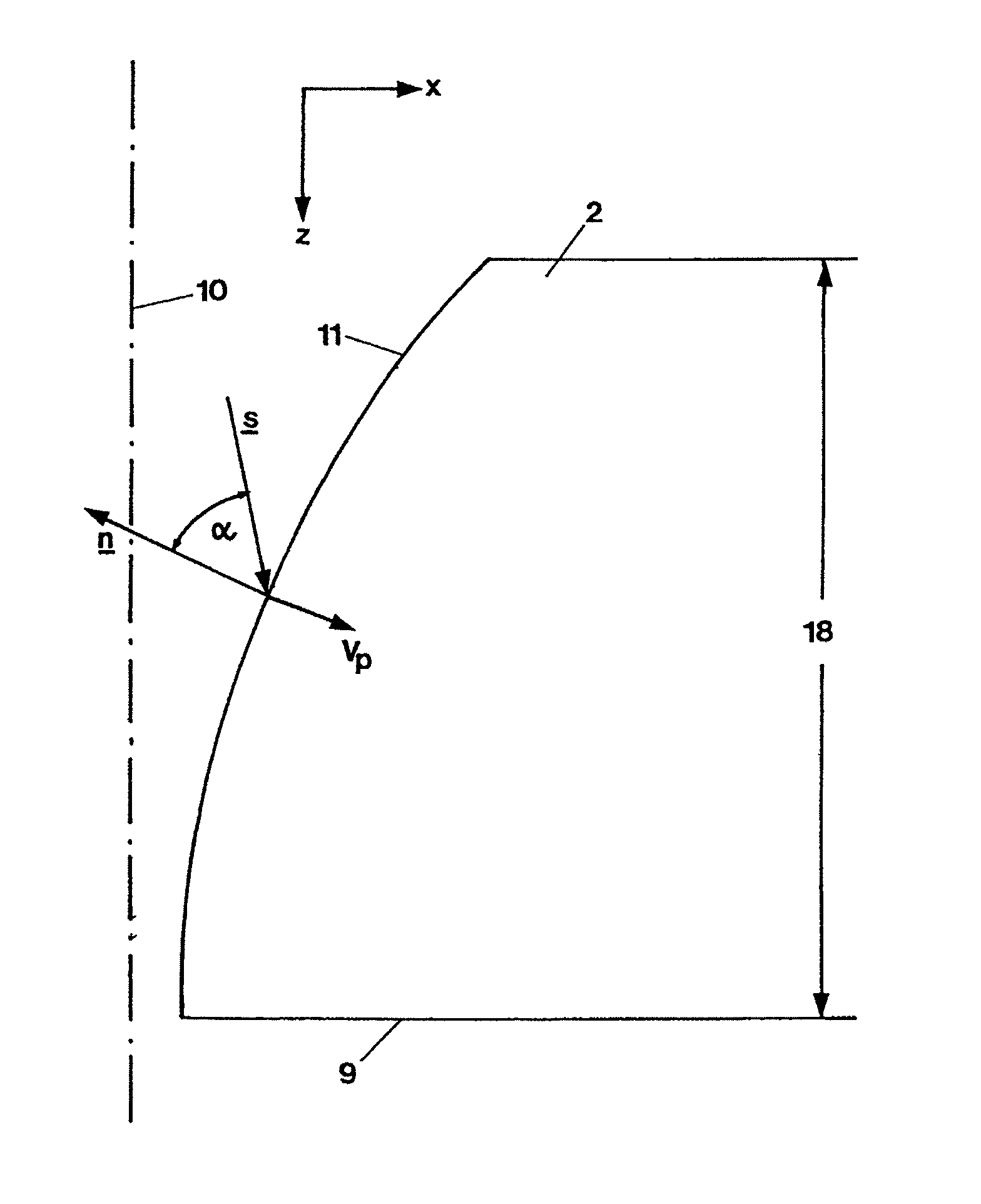
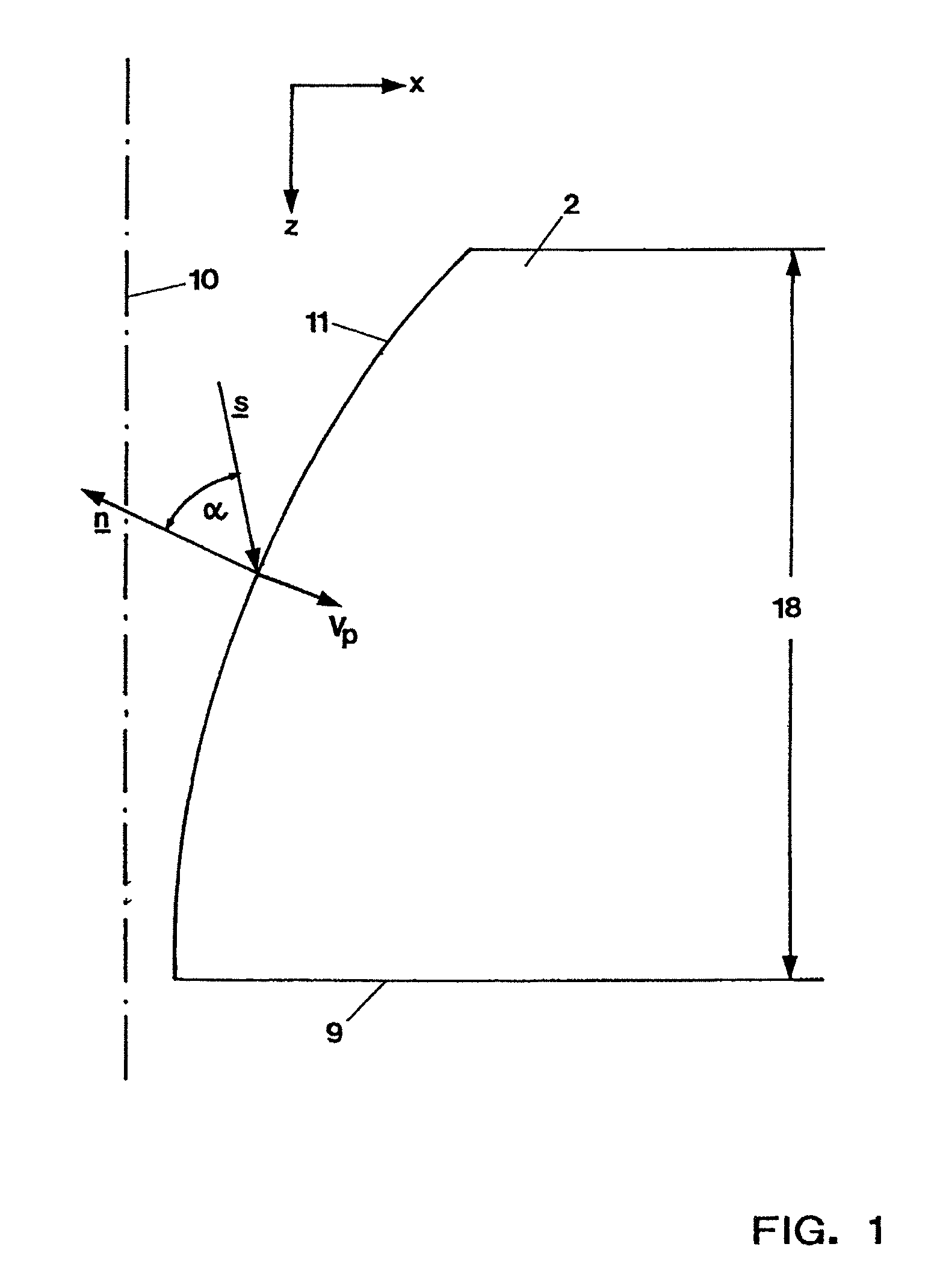
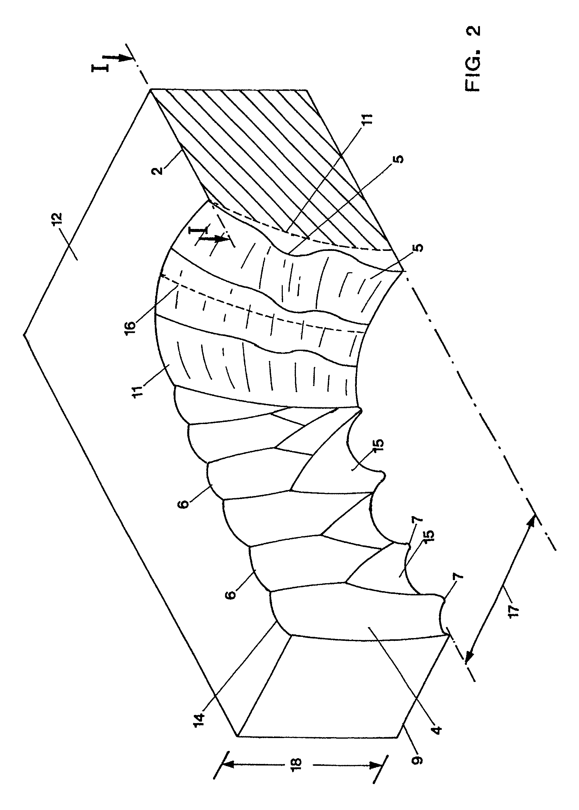
[0083]The preferred embodiments of the present invention will now be described with reference to FIGS. 1-5 of the drawings. Identical elements in the various figures are designated with the same reference numerals.

[0084]As has been explained, unnecessarily large fluctuations of the removal parameters that go beyond the unavoidable fluctuations and are reflected in the gouge image, should be identified as avoidable fluctuations and should at least be reduced.

[0085]FIG. 2 shows schematically a cut 1 generated with a laser beam along a removal line I-I (reference character 2) in a workpiece 3. A removal of the material in the cut 1 is carried out through fusing, possibly also evaporating, of the workpiece material with the support of a gas stream enveloping the laser beam. With regard to the material of the workpiece, the gas stream can be reactive but also inert.

[0086]The cut 1 is a cutting gap with two cut edges or removal edges 4, respectively (only one of which is shown in the “sem...


PUM

PropertyMeasurementUnit
Lengthaaaaaaaaaa
Timeaaaaaaaaaa
Thicknessaaaaaaaaaa

Abstract

A method for material removal to a predetermined removal depth from a workpiece employs a laser beam consisting of one or more sub-beams, each of the latter having a defined beam axis. The axis of the laser beam or the individual axes of the sub-beams are guided along a removal line at a predetermined travelling speed and the laser beam has a predetermined spatial energy flow density that defines a Poynting vector S with a value I0f (x) and a direction s, the spatial energy flow density creating a removal face with an apex formed by the leading part of the removal face in the removal direction and the face, creating a removal edge.

Description

BACKGROUND OF THE INVENTION[0001]The invention relates to a method for the material removal to a predetermined removal depth from a workpiece by means of a laser beam consisting of one or more sub-beams, each of the latter having a defined beam axis, whereby the axis of the laser beam or the individual axes of the sub-beams are guided along a removal line at a predetermined travelling speed and the laser beam has a predetermined spatial energy flow density that defines a Poynting vector S with a value I0f(x) and a direction s, the spatial energy flow density creating a removal face with an apex formed by the leading part of the removal face in the removal direction and said face creating a removal edge. The invention furthermore relates to a device for carrying out the method.[0002]Laser cutting is an established method for material removal through fusion at which the created removal depth encompasses the entire thickness of the workpiece. When cutting metals, the removal face is mo...

Claims


Application Information

Patent Timeline
IPC IPC(8): B23K26/38
CPCB23K26/0604B23K26/38B23K26/0617
Inventor SCHULZ, WOLFGANGPETRING, DIRKSCHNEIDER, FRANKNIESSEN, MARKUS
Owner FRAUNHOFER GESELLSCHAFT ZUR FOERDERUNG DER ANGEWANDTEN FORSCHUNG EV
Learn More