
Water conditioner assembly

a technology of water conditioner and assembly, which is applied in the direction of gravity filters, feed/discharge of settling tanks, specific water treatment objectives, etc., can solve the problems of concomitantly reducing the effective contact rate of the bed. the effect of reducing the bed channeling and increasing the operational efficiency of the filtration system

Inactive Publication Date: 2013-01-08
FIELD GEORGE RAYMOND
View PDF5 Cites 8 Cited by
  • Summary
  • Abstract
  • Description
  • Claims
  • Application Information

AI Technical Summary

Benefits of technology

This solution significantly increases the contact time between contaminants and media, improving filtration efficiency and extending operational runs by ensuring even distribution and reducing channeling, thus enhancing the performance of various filtration processes.

Problems solved by technology

The result is greater bed utilization which increases the operational efficiency of the filtration system, and a concomitant decrease in bed channeling permitting longer operational runs.
Channeling effects through the bed greatly decrease effective media bed contact rates due to incomplete bed usage and premature saturation.

Method used


Image

  • Water conditioner assembly
  • Water conditioner assembly
  • Water conditioner assembly

Examples


Embodiment Construction

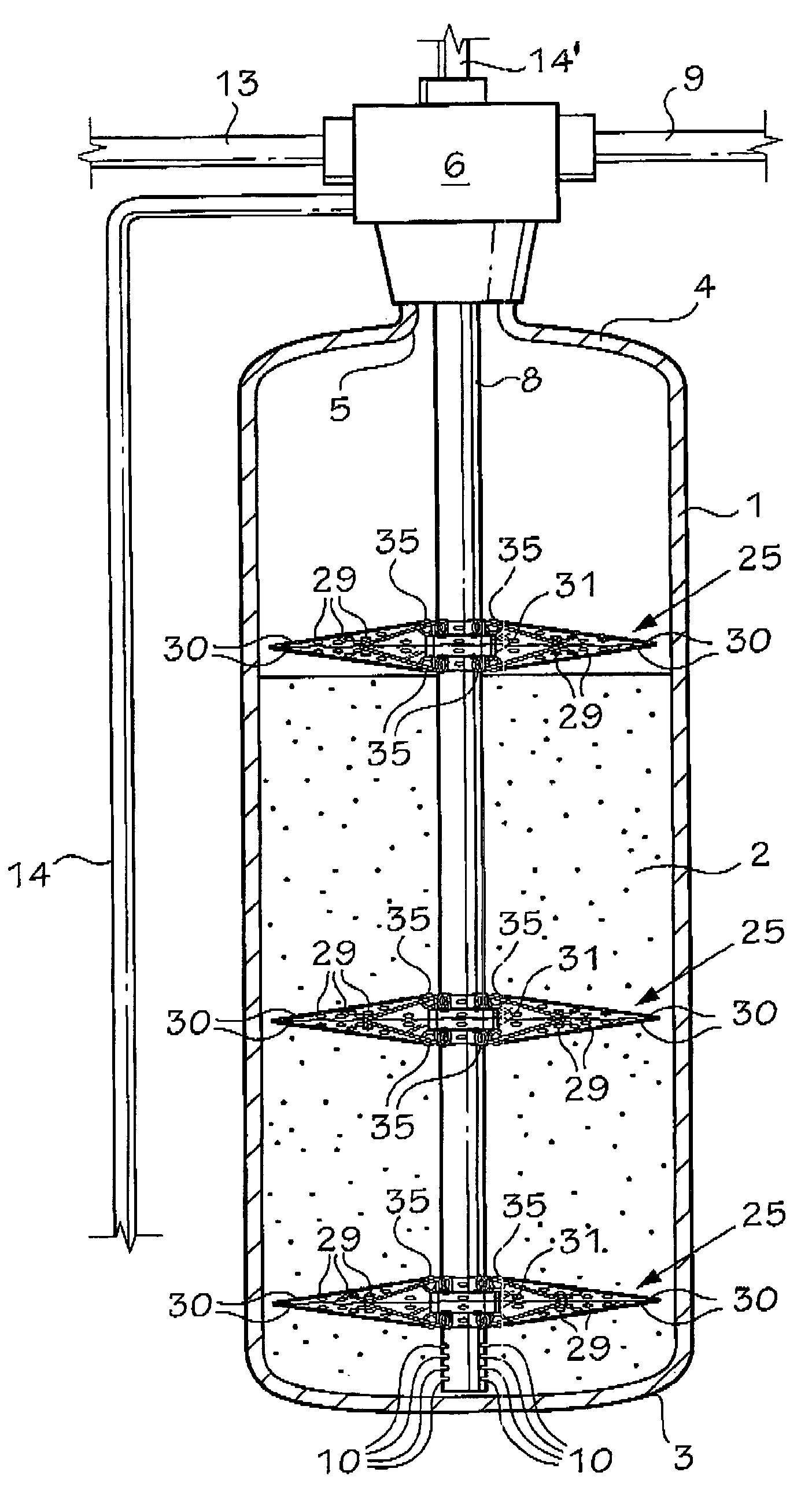
[0028]In accordance with the present invention, the single distributor 15 above the bed as described above is replaced by two or more distributors indicated generally at 25. It is worth noting that while FIG. 2 shows three distributors, in certain circumstances, depending upon bed size, only two distributors are required, one being on the top of the bed, and the other being in the bed immediately above the slits 10. In fact, there is no restriction as to the number of distributors in the bed.

[0029]As best shown in FIGS. 3 and 4, each of the distributors 25 is defined by a roughly disc-shaped body 26. Whereas the distributor described in CA 2,532,896 is designed to flex in one direction only, the distributor of the present invention is capable of flexing in both vertical directions. In order to achieve this effect, the disc-shaped body 26 is formed of top and bottom sheets 27 and 28, respectively. The sheets 27 and 28 are sealed together at their outer peripheries. A plurality of spo...


PUM

PropertyMeasurementUnit
flexibleaaaaaaaaaa
resistanceaaaaaaaaaa
flexibilityaaaaaaaaaa

Abstract

A distributor for use on a dip tube in the particulate bed of a water conditioner includes a sleeve mounted on the dip tube, a plurality of resilient vanes extending radially outwardly from the sleeve, thin membranes on the vanes, and holes in the membranes, whereby water flowing through the bed is evenly distributed throughout the bed and the bed is agitated by up and down flexing of the distributor in the bed.

Description

BACKGROUND OF THE INVENTIONField of the Invention[0001]This invention relates to a water conditioner assembly, and to a distributor for use in such an assembly.[0002]Water conditioners for domestic use include a tank containing a particulate material for softening water by removing calcium and magnesium salts. They are also used to remove a large number of organic and inorganic substances including iron and / or sulfur from the water. The typical apparatus has four cycles of operation including a service cycle, a backwash cycle, a regeneration cycle and a rinse cycle.[0003]During the service cycle, water is filtered through the bed of particulate material for use. The backwash cycle is used to remove contaminants from the bed. The bed is often regenerated during a regeneration cycle, and the bed is stabilized and flushed during the rinse cycle.[0004]During the service cycle, water flows in one direction (downwardly) through the bed and is discharged upwardly through a dip tube or the ...

Claims


Application Information

Patent Timeline
Patent Type & Authority Patents(United States)
IPC IPC(8): B01D24/40
CPCC02F1/42B01J49/0095B01J47/14B01J49/0086C02F1/006C02F2001/425C02F2303/16B01J49/75B01J49/85
Inventor FIELD, GEORGE RAYMOND
Owner FIELD GEORGE RAYMOND
Learn More