
Mainspring

a mainspring and spring technology, applied in the field of mainsprings, can solve the problems of high risk of delamination of laminates during forming operations, unreliable elasticity of springs, and theoretical shape of springs that do not take into account the behavior of laminated materials, etc., and achieve the effect of increasing the 2/e ratio, increasing the density of elastic energy, and constant torqu

Active Publication Date: 2013-01-08
ROLEX SA
View PDF20 Cites 14 Cited by
  • Summary
  • Abstract
  • Description
  • Claims
  • Application Information

AI Technical Summary

Benefits of technology

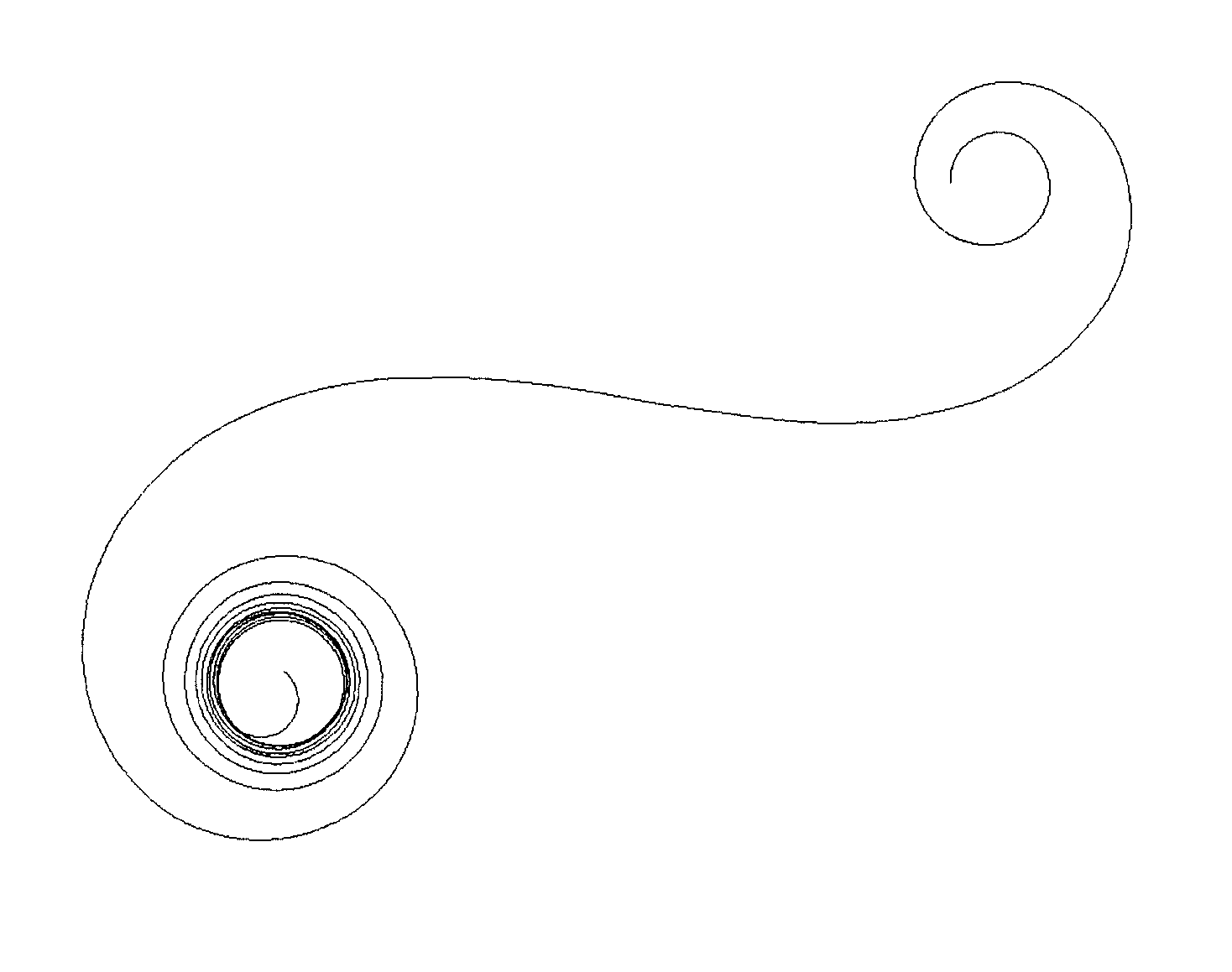
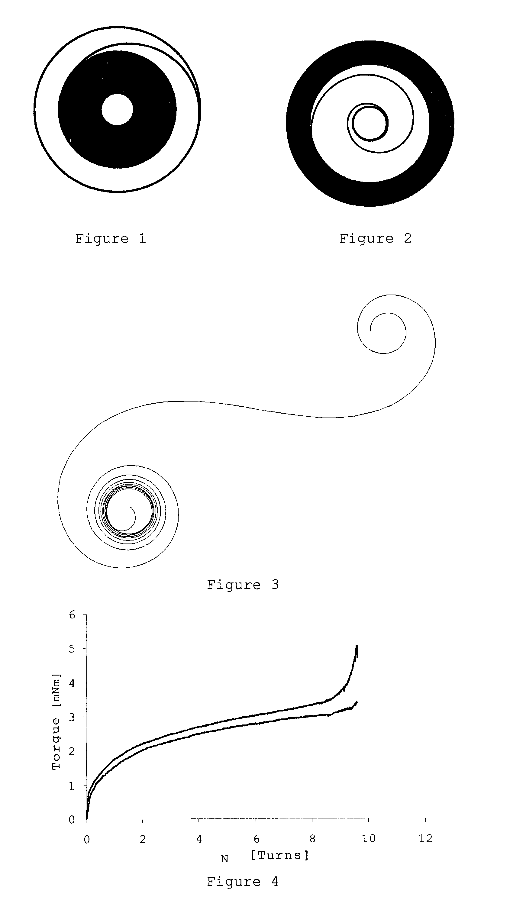
[0016]By producing a mainspring from a monolithic ribbon of metallic glass it is possible to fully benefit from the advantages of this class of material, in particular its ability to store a high density of elastic energy and to restore it with a remarkably constant torque. The maximum stress and Young's modulus values of such materials enable the σ2 / E ratio to be increased compared with conventional alloys, such as Nivaflex®.

Problems solved by technology

The major problem of such a strip is the high risk of delaminating the laminate during its forming operation and following the repeated winding and unwinding operations to which such a spring is subjected.
This risk is all the more acute when the resin ages badly and loses its properties.
Furthermore, the proposed modeling of the theoretical shape of the spring does not take into account the behavior of a laminated material.
It is obvious that such a solution cannot meet the torque, reliability and lifetime requirements that a mainspring must satisfy.
This also increases the level of stress available.
A single heat treatment would not enable the desired mechanical properties to be achieved for the conventional alloys.
Consequently, and unlike the Nivaflex® alloy, subsequent hardening by heat treatment is unnecessary.

Method used


Image

  • Mainspring
  • Mainspring
  • Mainspring

Examples


Embodiment Construction

[0022]In the example given below, the ribbons intended to form the mainsprings are produced by using the quench wheel technique (also called planar flow casting), which is a technique for producing metal ribbons by rapid cooling. A jet of molten metal is propelled onto a rapidly rotating cold wheel. The speed of the wheel, the width of the injection slot and the injection pressure are parameters that define the width and thickness of the ribbon produced. Other ribbon production techniques may also be used, such as for example twin-roll casting.

[0023]In the present example, the alloy Ni53Nb20Zr8Ti10Co6Cu3 is used. 10 to 20 g of alloy are placed in a delivery nozzle heated to between 1050 and 1150° C. The width of the nozzle slot is between 0.2 and 0.8 mm. The distance between the nozzle and the wheel is between 0.1 and 0.3 mm. The wheel onto which molten alloy is deposited is a wheel made of a copper alloy and is driven with a tangential velocity ranging from 5 to 20 m / s. The pressur...


PUM


Abstract

Mainspring for a mechanism driven by a motor spring, especially for a timepiece, formed from a ribbon of metallic glass material. This ribbon is monolithic and has a thickness of greater than 50 μm.

Description

BACKGROUND OF THE INVENTION[0001]The present invention relates to a mainspring for a mechanism driven by a motor spring, especially for a timepiece, formed from a metallic glass material.Description of the Prior Art[0002]A watch that includes a motor spring made of amorphous metal has already been proposed in EP 0 942 337. In fact, only a strip, formed from a laminate comprising ribbons of amorphous metal with thicknesses ranging up to 50 μm assembled with epoxy resin, is described in the above document. As a variant, it has been proposed to assemble strips by spot welding the two ends and the point of inflection of the free shape of the spring.[0003]The major problem of such a strip is the high risk of delaminating the laminate during its forming operation and following the repeated winding and unwinding operations to which such a spring is subjected. This risk is all the more acute when the resin ages badly and loses its properties.[0004]This solution would guarantee the functiona...

Claims


Application Information

Patent Timeline
Patent Type & Authority Patents(United States)
IPC IPC(8): G04B1/10
CPCG04B1/145
Inventor GRITTI, DOMINIQUEGYGER, THOMASVON NIEDERHAUSERN, VINCENT
Owner ROLEX SA
Learn More