Conveyor system

a conveying system and conveyor technology, applied in the direction of mechanical conveyors, conveyors, rotary conveyors, etc., can solve the problems of inability to guarantee the speed of conveying objects, the inability to keep the position of objects under control, and damage and wear of transported objects

Active Publication Date: 2013-01-08
FLEXLINK COMPONENTS
View PDF12 Cites 3 Cited by
  • Summary
  • Abstract
  • Description
  • Claims
  • Application Information

AI Technical Summary

Benefits of technology

[0005]Since the invention in particular elates to a conveyor system for transporting cylindrical objects such as roller or ball bearings having a relatively small length extension in relation to the diameter of the cylindrical object, it is desirable to arrange guide rails to give support to respective opposite end faces of said cylindrical object being defined by a cylindrical envelope surface and two opposite end faces. The relation between the length extension and the diameter generally lies within the interval ⅓— 1 / 10. In particular when it concerns roller or ball bearings, the variation in diameter, both in relative terms and actual terms, is greater than the variation of the length extension. Since the variation in the width direction is of a smaller magnitude, the magnitude of necessary adjustments of guide rails is smaller, and some times unnecessary. This will lead to reduced time consumption when adapting a conveyor system to a new product having different dimensions in when compared with a prior art system having the cylindrical objects positioned in horizontal position, that is with the symmetry axis vertical to a base surface of the conveyor.
[0006]In a first embodiment of the invention the conveyor system includes an elevation transport section, which is adapted to transport a cylindrical object from a first height level to a second height level, which elevation transport section includes an endless conveyer having a base surface extending along the transport path. In this embodiment the endless conveyor included in the elevation transport section is provided with a set of vertical protrusions arranged on the upper surface of the endless conveyer, which vertical protrusions includes an inclined portion sloping toward said base surface such that a cylindrical object transported on said elevation transport section will rest on said inclined portion under a contact force which by gravity is directed toward said base surface. This construction allows for a safe and stable transportation of the cylindrical object which is resting on the vertical protrusion with its respective end faces directed toward guide rails arranged on opposite sides of the conveyor. Since the cylindrical object is resting on the vertical protrusion rather than being supported on part of the lower edge as in the prior art vertical conveyer shown in FIG. 1, it may be possible to arrange the elevation transport section without guide rails.
[0007]In a preferred embodiment, the vertical protrusions include an upper and a lower inclined portion, where a cylindrical object transported on said elevation transport section will rest on said upper portion when transported in an upward direction and will rest on said lower portion when transported in a downward direction. Advantageously, the cylindrical object may shift its position from an upper inclined portion on a first vertical protrusion to the lower inclined portion on a second neighbouring vertical protrusion when the cylindrical object passes a crest in an elevation transport section. After having passed the crest the cylindrical object is allowed to roll under gravity forces from the upper inclined portion toward the next coming vertical protrusion to be caught by its lower inclined portion, which is positioned above the upper inclined portion of the same vertical protrusion when the vertical protrusion is moving in the downward direction. In the region of the crest it is, due to this partly uncontrolled movement of the cylindrical object which performs a relative movement in relation to the conveyor, advantageous to arrange guide rails limiting the freedom of movement of the cylindrical object in the lateral direction, that is in the width direction of the conveyor.
[0012]In a second embodiment of the invention, the conveyor system includes a storage section, which storage section includes a gate, which in closed state, prevents or limits release of transported cylindrical objects from said storage section, an endless conveyor and guide rails positioned on a respective side of said endless conveyor, which guide rails extend in the vertical direction to allow support for more than one layer of cylindrical objects positioned on top of each other on said endless conveyor. The cylindrical objects that are positioned on top of other conveyed cylindrical objects need the guide rails to not fall of the conveyer. This is particularly important for a conveyor system for transporting cylindrical objects such as roller or ball bearings having a relatively small length extension in relation to the diameter of the cylindrical object. It is desirable to arrange guide rails to give support to respective opposite end faces of said cylindrical object being defined by a cylindrical envelope surface and two opposite end faces. The relation between the length extension and the diameter generally lies within the interval ⅓— 1 / 10. Such an object would inevitably fall if the guide rails can not support the object. For the purpose of giving adequate support, the guide rails are preferably constituted by flat walls extending in the height direction from the conveyor to a suitable height of two of more layers. Walls will be considered to be flat as long as they do not include notches, gaps projections or other uneven structures that may prevent the cylindrical objects from climbing on top of each other and / or to move in the transport direction. It is furthermore advantageous to arrange the walls such that the transported object may be observed through the wall, as for example by arranging the walls by a small structured net, by a plate having small perforations arranged thereon or by a translucent or transparent glass or plastic wall. When the gate opens, stored cylindrical objects will be released from the storage section.
[0013]In a preferred embodiment, the storage system comprises an endless conveyor which is provided with base surface having a set of humps or cut-outs arranged to transfer a momentum in an upwards direction to a cylindrical object positioned in the storage section when said hump or cut-out is passing said cylindrical object facilitating the forming of a plurality of layers of cylindrical object. The uneven surface of the base surface of the endless conveyor ensures that a distortion to the movement in the forward direction is generated, which distortion facilitates for allowing cylindrical objects to climb on top on other cylindrical objects when stored in the storage section.
[0017]According to a fourth embodiment, the conveyor system includes, at least along a portion of the conveyor path, a plurality of parallel conveyer paths each being separated by guide rail portion, where said to guide rails are arranged to give support to respective opposite end faces of said cylindrical objects. Preferably, a converging module is arranged at the end of the plurality of parallel conveyor paths, which converging module reduces the number or parallel conveyer paths by allowing entry from at least two parallel paths to a single path.

Problems solved by technology

Such transportation may lead to damage and wear on the transported articles.
Without active transportation, the velocity of the conveyed objects can not be guaranteed.
Furthermore, the position of the objects can not be kept under control.

Method used


Image

  • Conveyor system
  • Conveyor system
  • Conveyor system

Examples


Embodiment Construction

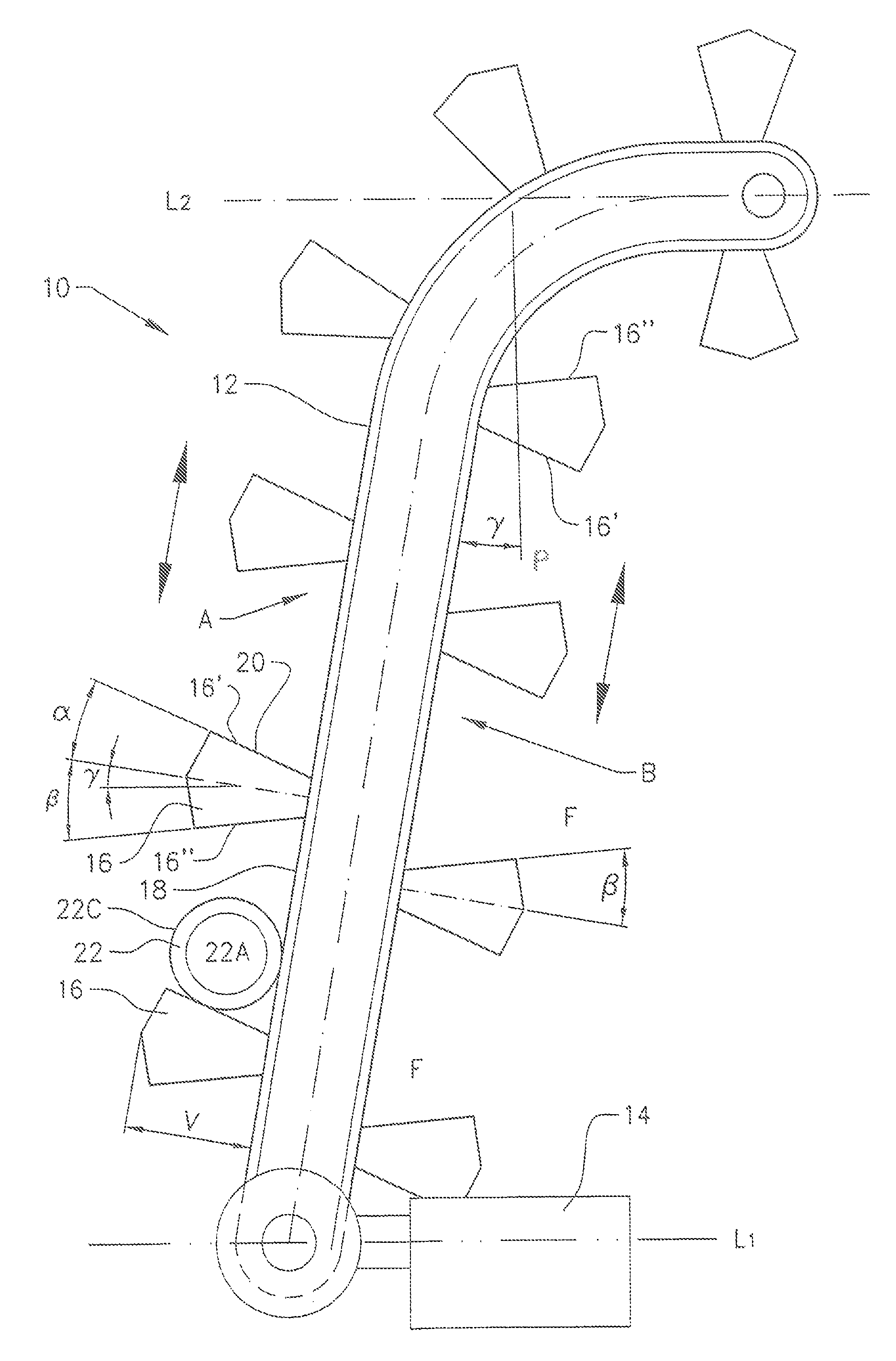
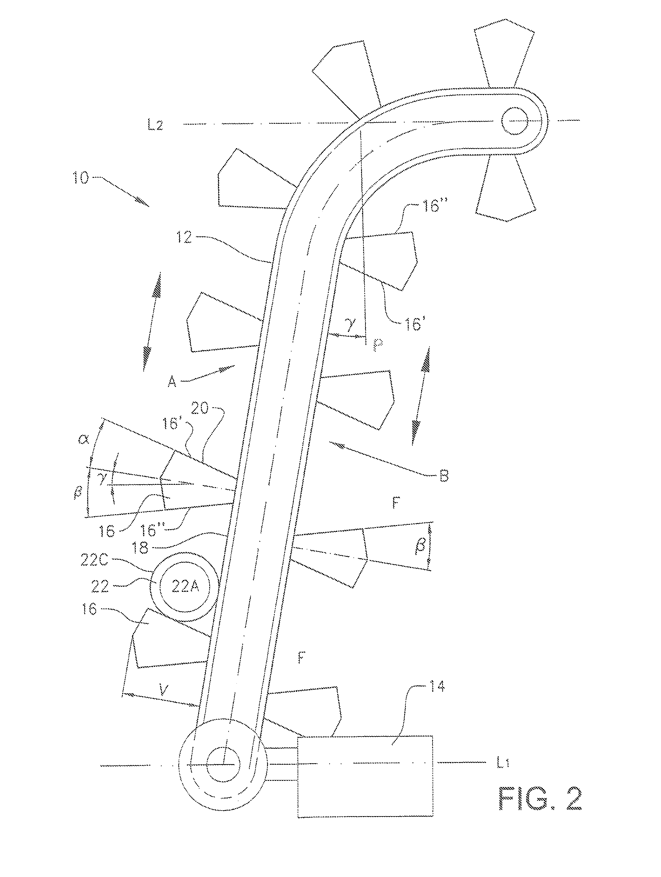
[0045]In FIG. 2 an elevation transport section 10 forming part of a conveyor system for transporting cylindrical objects 22 is shown. The cylindrical object includes two opposite end faces 22A and an envelope surface 22C. The elevation transport section 10 is arranged to transport a cylindrical object from a first height level L1 to a second height level L2. In the embodiment shown in FIG. 2 the elevation transport section forms a transportation path which is inclined in relation to a vertical plane P at an angle γ. As shown in FIG. 2, the elevation transport section has a first side A with an inclination of less than 90° and a second side B having an inclination exceeding 90°. It is possible but not necessarily to use both sides of the elevation transport section for transportation of goods. One side of the elevation transport section may be used as a transport path while the other opposite side is used as a return path. The transport path may include portions which have an inclina...


PUM


Abstract

A conveyor system for transporting cylindrical objects is disclosed including an endless conveyor arranged in a transport path, a drive for feeding the endless conveyor, guide rails for restricting lateral movement of cylindrical objects transported on the endless conveyor, an elevation transport section adapted to transport the cylindrical objects from a first height to a second height and including the endless conveyor having a base surface extending along the transport path, the endless conveyor including vertical protrusions extending outwardly from the base surface of the endless conveyor and including a front wall with an inclined portion sloping towards the base surface, such that a cylindrical object transported on the elevation transport section can rest on the inclined portion under a contact force directed towards the base surface by gravity.

Description

TECHNICAL FIELD [0001]The present invention relates to a conveyor system according to the preamble of claim 1. Generally the invention relates to a conveyor system arranged for transportation of cylindrical objects. In particular the invention relates to a conveyor system for actively transporting cylindrical objects, such as roller or ball bearings, having a relatively small length extension in relation to the diameter of the cylindrical object. The relation between the length extension and the diameter generally lies within the interval ⅓— 1 / 10.BACKGROUND ART[0002]In known conveyor systems for cylindrical objects, the cylindrical objects are generally transported lying down with one of the end faces of the cylindrical object facing a base surface of the conveyor. In known conveyor systems transportation in the vertical direction is performed in the same manner. An example of such a prior art vertical conveyer is shown in FIG. 1. Since the cylindrical object 1 does not adhere to a ...

Claims


Application Information

Patent Timeline
Patent Type & Authority Patents(United States)
IPC IPC(8): B65G17/32
CPCB65G15/42B65G17/12B65G17/40B65G17/46B65G21/2072B65G47/846B65G47/32B65G2201/0232
Inventor OHMAN, MICHAELCOX, STEVE
Owner FLEXLINK COMPONENTS
Why Eureka
Try Eureka