
Flexible pixel element and signal distribution means

a technology of flexible pixel elements and signal distribution means, which is applied in the direction of static indicating devices, instruments, electroluminescent light sources, etc., can solve the problems of inelegant and wasteful implementation of video components, lack of the desired effect of shaped video components, and inability to display graphics that can be displayed on electronic display devices. achieve the effect of reducing the number of connectors and conductors, reducing the number of electronic display devices, and facilitating replacemen

Active Publication Date: 2013-01-01
DAKTRONICS
View PDF119 Cites 68 Cited by
  • Summary
  • Abstract
  • Description
  • Claims
  • Application Information

AI Technical Summary

Benefits of technology

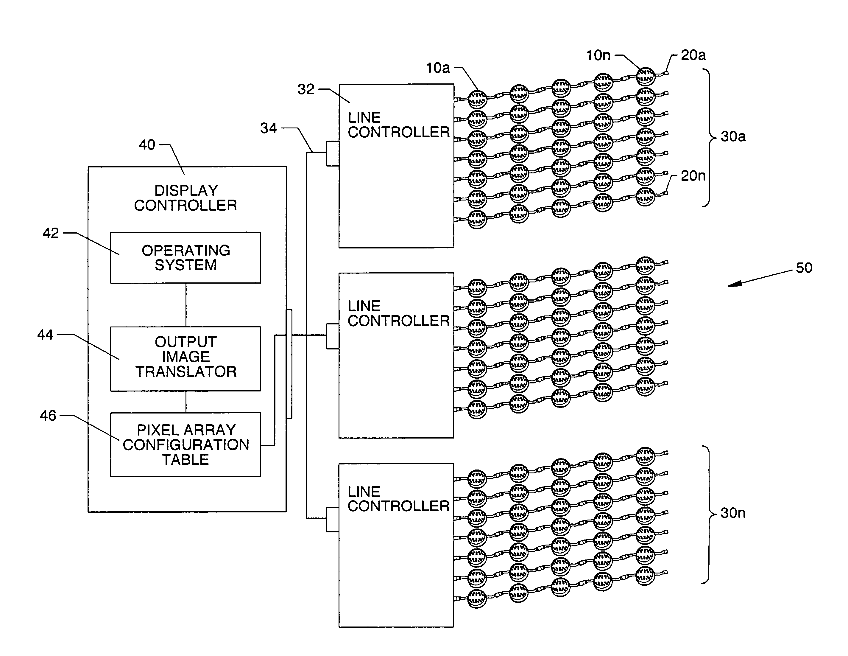
The present invention provides a flexible pixel string system that can be applied to irregular shapes and surfaces, such as channel letter displays, pillars, and curved walls, to create large-scale electronic display devices and dynamic electronic signage and light effects. Additionally, a display controller is included that converts conventional graphical image data into visual image data and display control signals for the flexible pixel elements, eliminating the need for special addressing or configuration means to uniquely identify the placement or position of the flexible pixel elements.

Problems solved by technology

The graphical content that can be displayed on electronic display devices is technology-dependent and generally limited by the light-emitting elements used to produce visual images.
However, such use of rectangular-grid video components is inelegant and wasteful in implementation, while the end result often lacks the desired effect that shaped video components can provide.
Moreover, rectangular-grid video components and control system means are inadequate for creating the type of custom shaped electronic display devices that are becoming increasingly popular.
Custom shaped electronic displays may be non-rectilinear and non-planar (e.g., circular, cylindrical and spherical displays), making the use of rectangular-grid video components to produce custom shaped electronic displays difficult to execute and expensive to produce.
However, electronic display devices and signage that use rectangular-grid video components are more easily repaired than those that use shaped video components, since rectangular-grid video components are easily replaced when they fail or are damaged, while shaped video components must be re-fabricated to match the failed or damaged components.
Additional problems in the prior art result from limitations of technology used to distribute signals, such as operating power, image data and display control signals, to pixel elements ganged together in large scale displays and signage.
First, power loss and signal degradation across long run lengths of conductors limits the distance the off-board pixel element driver PCBs can reside from the pixel elements they drive, thus limiting the size of the electronic display device to the maximum conductor run length and restricting optimal placement of remote display controllers.
Second, limitations on the number of pixel elements that can be serviced by a single driver PCB requires the use of multiple driver PCBs to service a large plurality of pixel elements embodied within large scale electronic displays and signage.
Third, the use of multiple driver PCBs requires the concomitant use of expensive power and signal cables to service the pixel elements.
Finally, the multiplicity of driver PCBs, power cables and signal cables, in addition to the large plurality of pixel elements inherent in the design of large scale electronic display devices and signage, creates a vulnerable design architecture having complex wiring with many connection points and potential points of failure.
Moreover, while the prior art provides for serial-connection of pixel elements in electronic display devices and signage, the data transmission distance between pixel elements is limited to short distances and still requires a large number of power and signal conductors to transmit operating power, image data and control signals between pixel elements.
Another problem inherent in the prior art is means and methods to protect a vulnerable design architecture having many potential points of failure and delicate electronic components, such as pixel elements and drivers, from failure due to harsh environmental conditions and inclement weather, a particular problem with outdoor or exterior electronic displays and signage.
Not only does this add to the cost of already expensive large scale exterior electronic displays and signage, but producing enclosures that conform to irregular shaped surfaces can be a complex and costly undertaking.
Moreover, such an enclosure constitutes a single failure point, wherein any failure of the enclosure exposes all the connection points and delicate electronic components contained therein to potential failure.
Finally, collective enclosures are subject to over-heating from both internal and external sources including component power dissipation and solar radiation.
As a result, design and production of such devices are slow and inefficient, production costs are prohibitive, and outcomes are often inelegant and failure prone.

Method used


Image

  • Flexible pixel element and signal distribution means
  • Flexible pixel element and signal distribution means
  • Flexible pixel element and signal distribution means

Examples


Embodiment Construction

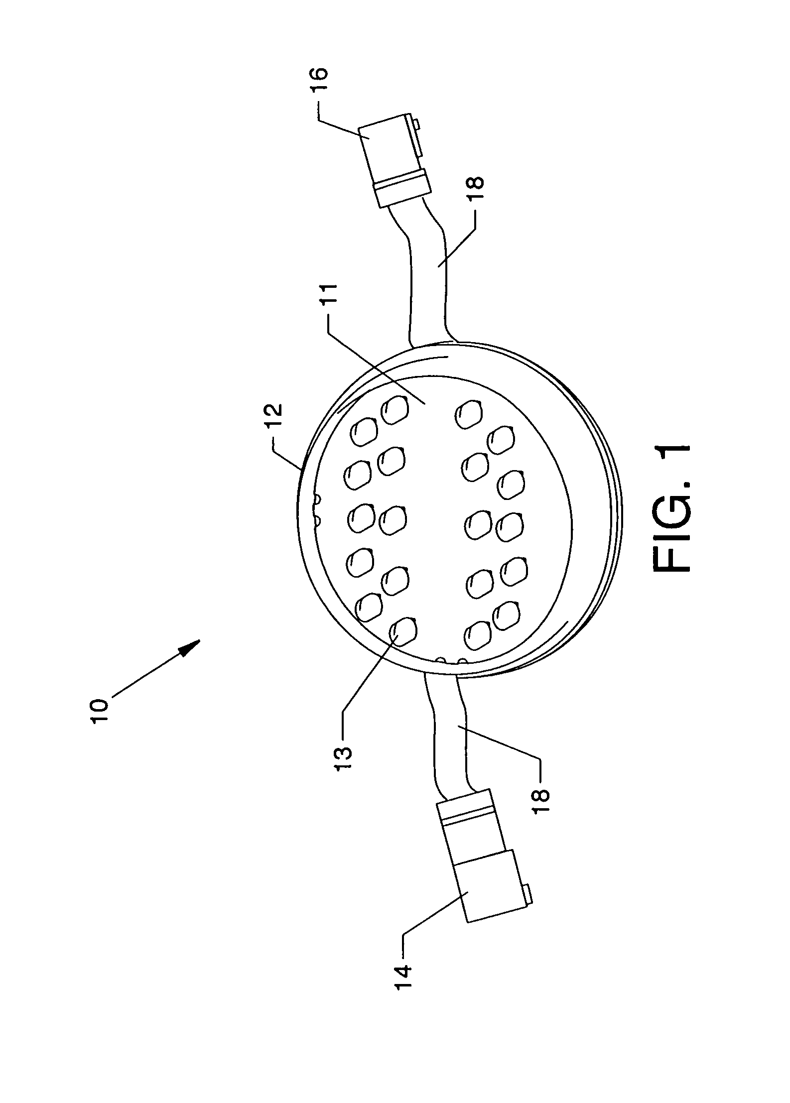
[0042]FIG. 1 is an isometric view of a preferred embodiment of discreet flexible pixel element 10 of the present invention. Discreet flexible pixel element 10 embodies a printed circuit board 11, on which various electrical components (described hereinafter) are mechanically joined by operative electrical connection, a plurality of light-emitting elements 13 hermetically sealed within case 12, input connector 14, output connector 16 and flexible cables 18. Light-emitting elements 13 illuminate when energized by on-board element drivers (not shown) to produce visual output in the form of emitted light. In a preferred embodiment, light-emitting elements 13 comprise a plurality of red, green and blue (RGB) colored LEDs.

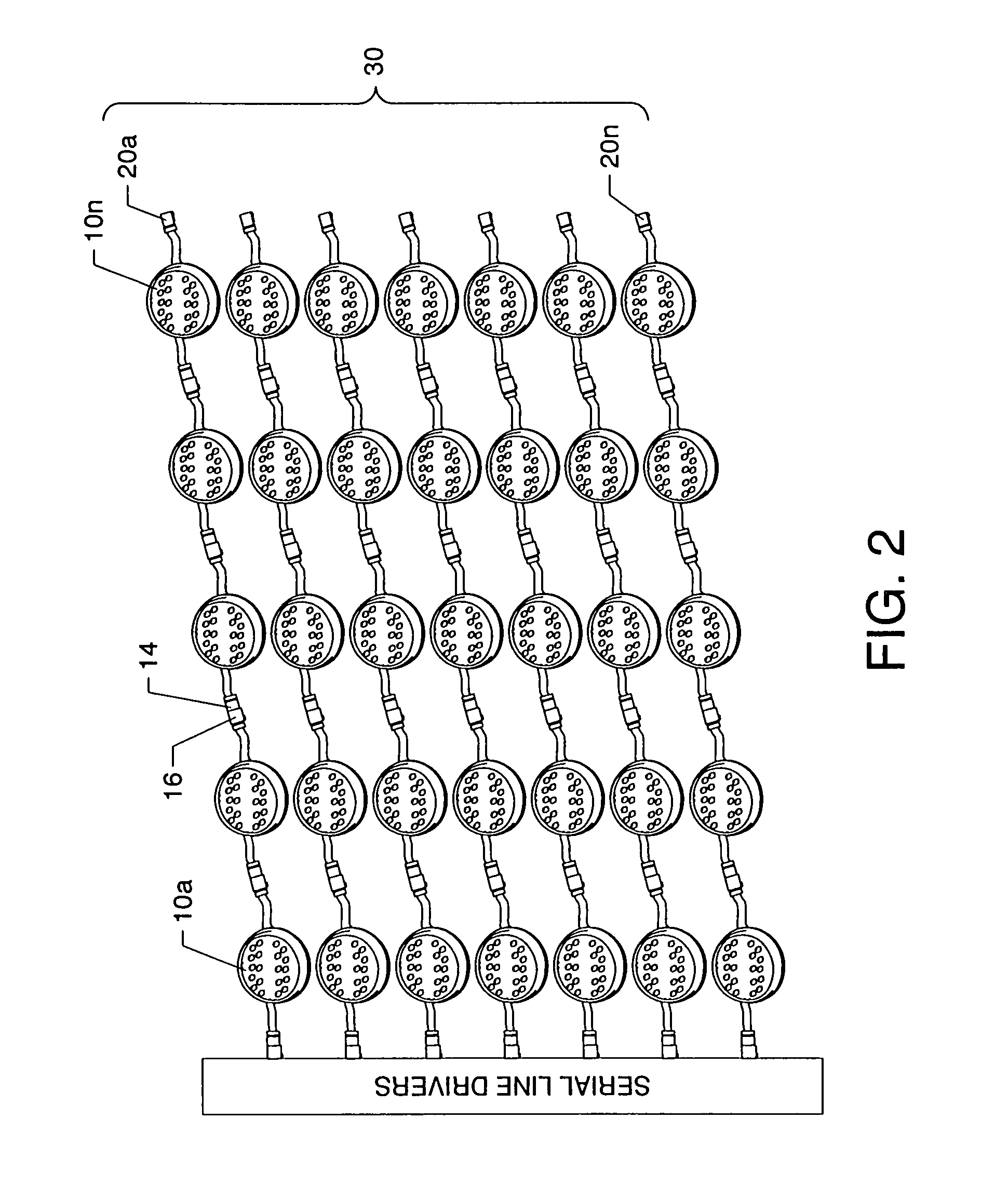
[0043]FIG. 2 is a simplified connection diagram depicting a plurality of discreet flexible pixel elements 10a-10n connected in series to embody flexible pixel string 20a, wherein output connector 16 of a given discreet flexible pixel element 10 is operatively joined in s...


PUM


Abstract

Discrete flexible pixel elements are hermetically sealed from the environment and comprise unitary, self-contained replaceable modules which enable efficient, economical production of large scale, free-form electronic displays, signs and lighting effects for outdoor use. The method and means for producing hermetically sealed discrete flexible pixel elements include encapsulation means, exterior casement means, and cable connector means.

Description

CROSS REFERENCES TO RELATED APPLICATIONS[0001]This application is a continuation-in-part of patent application Ser. No. 10 / 965,127 filed on Oct. 14, 2004 now abandoned, entitled “Flexible Pixel String Software and Method.”[0002]This application claims priority from the earlier filed U.S. Provisional Application No. 60 / 926,706 filed Apr. 27, 2007, entitled “Flexible Pixel Assemblies for Mounting on Irregular Surfaces,” and is hereby incorporated into this application by reference as if fully set forth herein.[0003]This application is related to U.S. utility patent application Ser. No. 10 / 965,133 filed on Oct. 14, 2004, entitled “Flexible Pixel String Hardware and Method,” which is pending.[0004]This application is also related to U.S. utility patent application entitled “Flexible Pixel Element Fabrication and Sealing Method”, application Ser. No. 11 / 895,424, filed concurrently herewith, a copy of which is attached and the disclosure of which is incorporated by reference as if fully s...

Claims


Application Information

Patent Timeline
Patent Type & Authority Patents(United States)
IPC IPC(8): H01L33/00
CPCG06F3/1446H05B33/0803H05B33/0815H05B33/0857G09G3/32G09G2300/0426G09G2370/045H05B47/00
Inventor WENDLER, BRETT D.BRAVEK, ERIC S.GREBEL, ERICH J.
Owner DAKTRONICS
Learn More