Apparatus and method for compensating for stress deformations in a press

a technology of stress deformation and apparatus, applied in the direction of presses, press rams, shaping tools, etc., can solve the problems of extreme stress on hydraulic presses, deformation of hydraulic presses and tools, and so on, and achieve the effect of uniform compression depth

Inactive Publication Date: 2013-01-01
AUTOMATION PRESS & TOOLING AP&T
View PDF11 Cites 0 Cited by
  • Summary
  • Abstract
  • Description
  • Claims
  • Application Information

AI Technical Summary

Benefits of technology

The present invention allows for the apparatus to be made with a thickness that can compensate for any deformations that occur. This makes it easier to compensate for new tools that are placed in the press, resulting in shorter retooling time and higher production capacity. Essentially, the apparatus can adjust its thickness as needed.

Problems solved by technology

Hydraulic presses operate at high pressure, which results in the parts in the hydraulic press, as well as the tool placed in the hydraulic press, being subjected to extreme stresses.
These stresses are so great that the parts of the hydraulic press and the tool are deformed.
This deformation results in the pressure distribution in those tools which are to impart to the final product its configuration and appearance becoming uneven.
This will have as a result that the end product will be unevenly formed and will have an unacceptable quality.
The drawbacks inherent in prior art technology are numerous.
In the utilisation of shims, there is, granted, obtained a compensation for the deformation, but accurate setting is required and, this not withstanding, the compensation will be incomplete and above all not constant, but the compensation itself must be repeated at regular intervals.
This results in unnecessary time loss for the compensation which lowers production capacity for the press.
Another drawback inherent in shims is further that the thickness of the shims is given and not variable.
Accuracy using shims is also difficult to achieve, which has a negative effect on the quality of the product produced using the tool in the press.
The drawback inherent in cambering or crowning is that the arching which is created is difficult to change in a simple manner if required.
This lack of flexibility also results in considerable time loss when a new tool is to be positioned in a press.
Hence, cambering or crowning shows a low level of flexibility.
In addition, there has been a lack of an apparatus which simply and rapidly can be adapted to a new tool disposed in a press.

Method used


Image

  • Apparatus and method for compensating for stress deformations in a press
  • Apparatus and method for compensating for stress deformations in a press
  • Apparatus and method for compensating for stress deformations in a press

Examples


Embodiment Construction

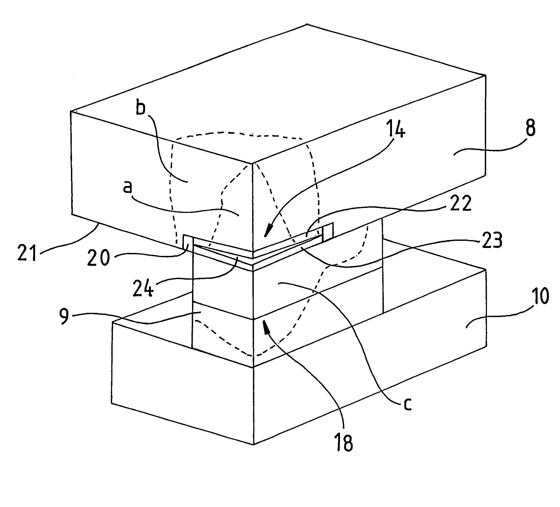
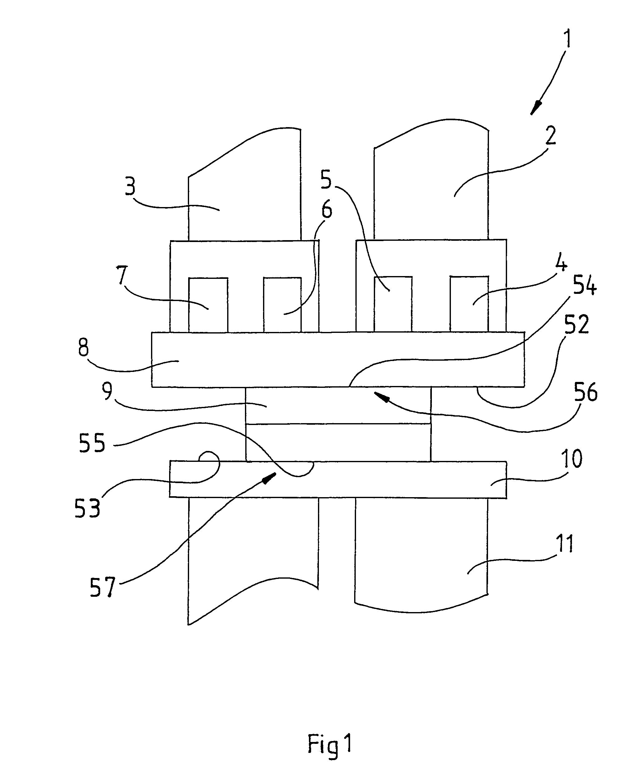
[0023]FIG. 1 shows a hydraulic press 1 in which two large press cylinders 2, 3 together with four smaller press cylinders 4, 5, 6 and 7 act on a slide 8. Beneath the slide, a tool 9 is disposed which rests on a work table 10. The lower part 11 of the hydraulic press is disposed beneath the work table 10.

[0024]The tool 9 is of dual construction and has an upper part which is fixed in the slide 8 and a lower part which is fixed on the work table 10.

[0025]The illustrated type of hydraulic press 1 operates as follows. Between the slide 8 and the work table 10, the tool 9 is positioned. In this tool 9, there is placed a work piece (blank) which is to be formed by this tool. When the work piece is in place in the tool 9, the slide 8 presses the tool 9 against the work table 10 with the aid of the press cylinders 2, 3, 4, 5, 6 and 7. Once these press cylinders have acted for a given time interval which is sufficiently long for the work piece placed in the tool 9 to have achieved the desire...


PUM


Abstract

An apparatus is provided for compensating for such deformations as occur in operation in first and second clamping surfaces intended for a tool in a press. The clamping surfaces are reciprocally moveable towards and away from one another in order to move a first and second part of the tool towards and away from one another, and the first and second tool parts have a first and second abutment surface for abutment against the first and second clamping surfaces and the deformations cause uneven pressure in at least one contact region between the tool and the clamping surfaces. According to the present invention, there is disposed, in at least one contact region between a clamping surface and an abutment surface, a power unit which, on activation, is operative to press, away from the clamping surface located in the contact region at least a part of the abutment surface of the tool located there.

Description

BACKGROUND[0001](1) Field of the Invention[0002]The present invention relates to an apparatus for compensating for such deformations as occur in first and second clamping surfaces intended for a tool in a press, the clamping surfaces being reciprocally moveable towards and away from one another for moving a first and a second part of the tool towards and away from each other, respectively, such deformations generating an uneven pressure in at least one area of contact between the tool and the clamping surfaces.[0003](2) Prior Art[0004]In hydraulic presses, tools are positioned by means of which different objects are compression moulded to the desired configuration and appearance. Hydraulic presses operate at high pressure, which results in the parts in the hydraulic press, as well as the tool placed in the hydraulic press, being subjected to extreme stresses. These stresses are so great that the parts of the hydraulic press and the tool are deformed. This deformation results in the ...

Claims


Application Information

Patent Timeline
Patent Type & Authority Patents(United States)
IPC IPC(8): B30B15/06B30B15/00
CPCB30B15/007
Inventor KARLSSON, MIKAELWALKIN, BENGT
Owner AUTOMATION PRESS & TOOLING AP&T
Why Eureka
Try Eureka