
Atomizing desuperheater shutoff apparatus and method

a technology of superheater and atomizer, which is applied in the direction of lift valve, temperatue control, flow mixer, etc., can solve the problems of accelerated operational failures and/or premature wear of internal parts, and achieve the effects of reducing end user parts replacement costs, reducing margins, and being more durabl

Active Publication Date: 2012-12-18
CELEROS FLOW TECH LLC
View PDF5 Cites 6 Cited by
  • Summary
  • Abstract
  • Description
  • Claims
  • Application Information

AI Technical Summary

Benefits of technology

The MADV effectively maintains fluid temperatures, reduces leakage, and increases service life by integrating the cooling liquid control valve, achieving tight seat leakage shutoff and minimizing maintenance costs through a modular design and durable materials.

Problems solved by technology

The resulting high thermal stresses and different thermal expansions of the internal parts create the potential for accelerated operational failures and / or premature wear of internal parts.

Method used


Image

  • Atomizing desuperheater shutoff apparatus and method
  • Atomizing desuperheater shutoff apparatus and method
  • Atomizing desuperheater shutoff apparatus and method

Examples


Embodiment Construction

[0026]The many features and advantages of the invention are apparent from the detailed specification, and thus, it is intended by the appended claims to cover all such features and advantages of the invention which fall within the true spirit and scope of the invention. Further, since numerous modifications and variations will readily occur to those skilled in the art, it is not desired to limit the invention to the exact construction and operation illustrated and described, and accordingly, all suitable modifications and equivalents may be resorted to, falling within the scope of the invention.

[0027]There has thus been outlined, rather broadly, certain embodiments of the invention in order that the detailed description herein may be better understood, and in order that the present contribution to the art may be better appreciated. There are, of course, additional embodiments of the invention that will be described below and which will form the subject matter of the claims appended ...


PUM

PropertyMeasurementUnit
angleaaaaaaaaaa
durable corrosion resistantaaaaaaaaaa
temperatureaaaaaaaaaa

Abstract

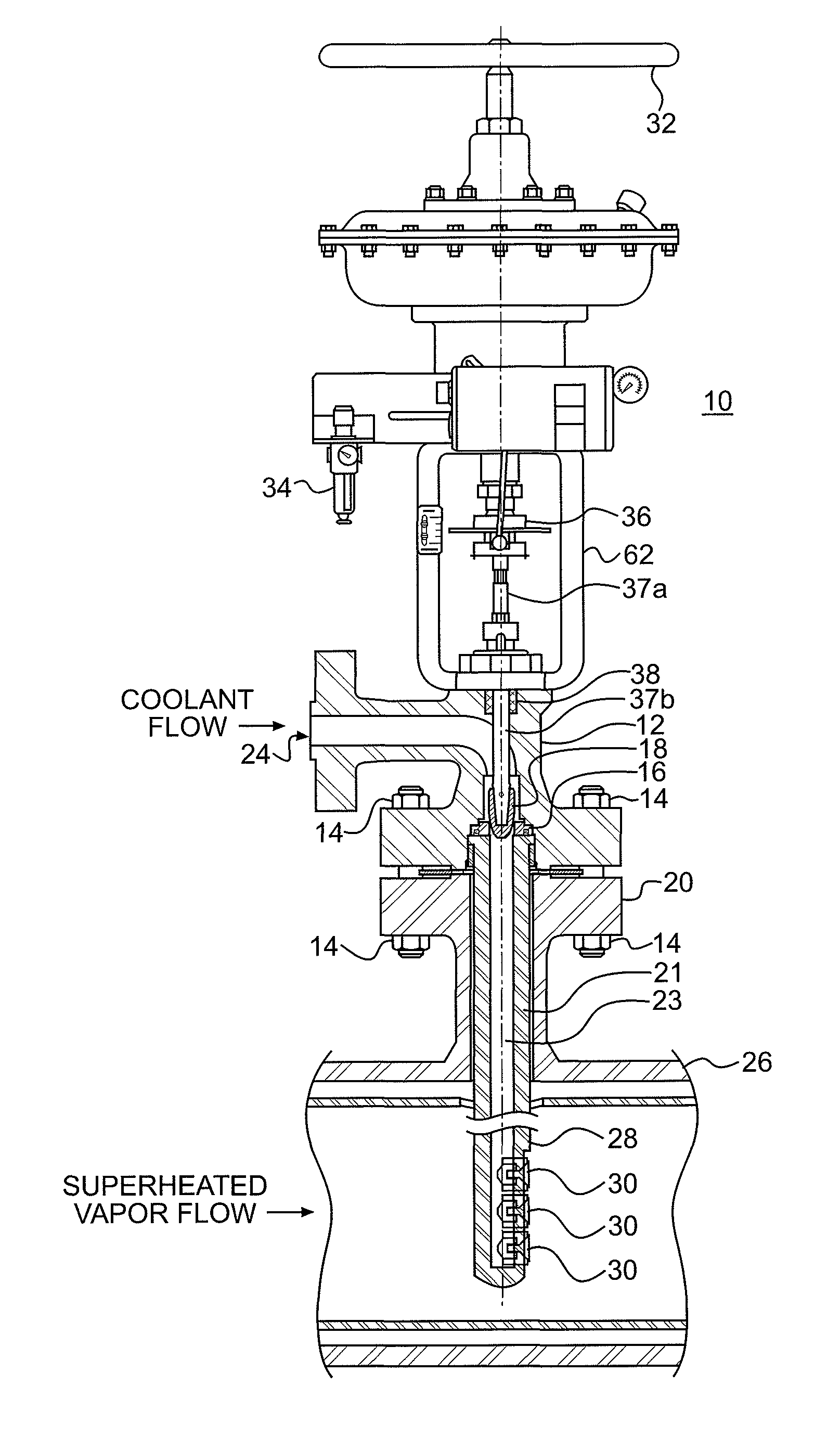
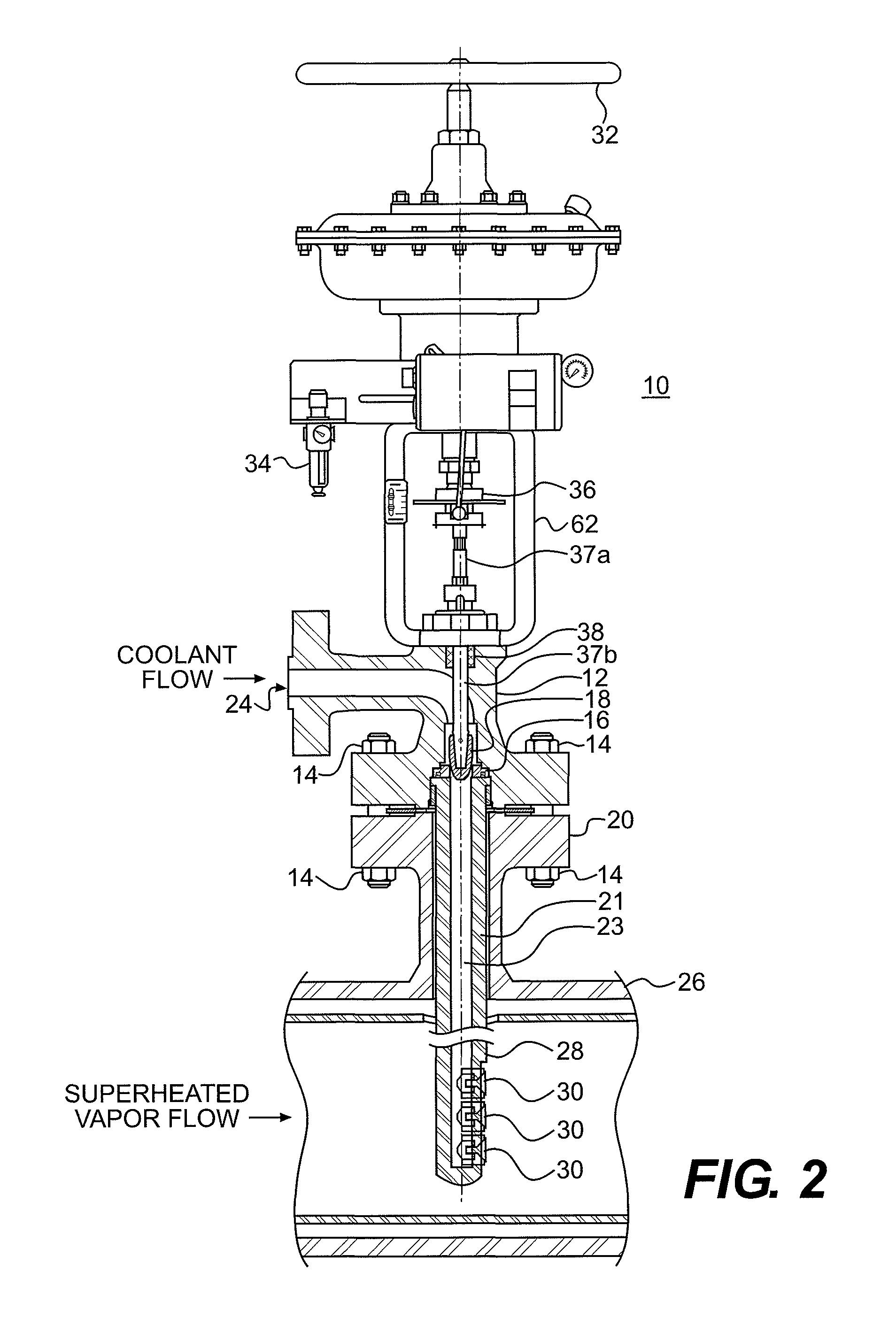
The present invention is directed to a desuperheater spraying valve assembly. More particularly, the invention provides a new and improved valve assembly, whereby cooling liquid may be controllably injected into a gas or a liquid stream, typically steam, to selectively maintain the gas or liquid at a predetermined temperature level. In a possible embodiment of the present invention, a class V valve assembly is disclosed. It comprises an actuator coupled to a plug with a valve seat in the proximity of said plug. The plug is affixed to an actuator rod which transverses the body of the valve assembly. A spray tube may be affixed to said valve seat and at least one spray nozzle is affixed to a to the spray tube. The plug and said valve seat are conical in shape as to when said plug is inserted into said valve, they form a seal.

Description

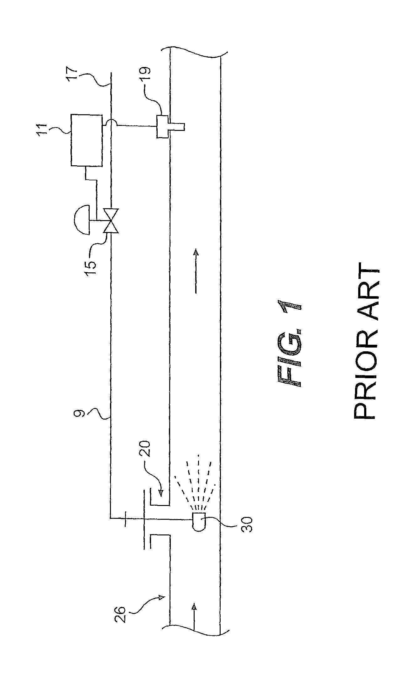
BACKGROUND OF THE INVENTION[0001]The present invention is directed to a spray desuperheater apparatus and method. More particularly, the present invention is directed to an improved desuperheater valve assembly, which may have a plurality of nozzles affixed to the spray assembly. The aforementioned assembly allows for the controlled injection of a cooling liquid into a superheated fluid to selectively reduce the temperature of the superheated fluid and maintain the downstream flow at a predetermined temperature level.[0002]Superheated fluid is fluid that is at a temperature that is higher than the boiling point of the fluid. Many industrial applications operate most efficiently using a fluid that is saturated or only slightly superheated, but many fluid generators tend to produce a fluid that is excessively superheated. Excessive temperatures (superheat) may damage system components, adversely affect the efficiency of operation or quality of the product being manufactured. The proce...

Claims


Application Information

Patent Timeline
Patent Type & Authority Patents(United States)
IPC IPC(8): G05D23/13B01F5/04B01D47/06B01F25/70
CPCF22G5/123F16K1/385F22G5/12Y10T137/0324Y10T137/8766
Inventor IGNATAN, VEACESLAVFETTERMAN, ROBERT L.
Owner CELEROS FLOW TECH LLC
Learn More