Eureka AIR delivers breakthrough ideas for toughest innovation challenges, trusted by R&D personnel around the world.

Multi-domain liquid crystal display

a liquid crystal display and multi-domain technology, applied in static indicating devices, instruments, non-linear optics, etc., can solve the problems of insufficient strength of fringe fields generated by the formation of slits 206, and achieve the effects of reducing the area of disclination, increasing the light-transmittance of an lcd, and strong field strength

Inactive Publication Date: 2012-12-11
WINTEK CORP +1
View PDF23 Cites 0 Cited by
  • Summary
  • Abstract
  • Description
  • Claims
  • Application Information

AI Technical Summary

Benefits of technology

[0009]The invention provides a multi-domain liquid crystal display capable of solving the problems of conventional designs and having excellent luminous uniformity.
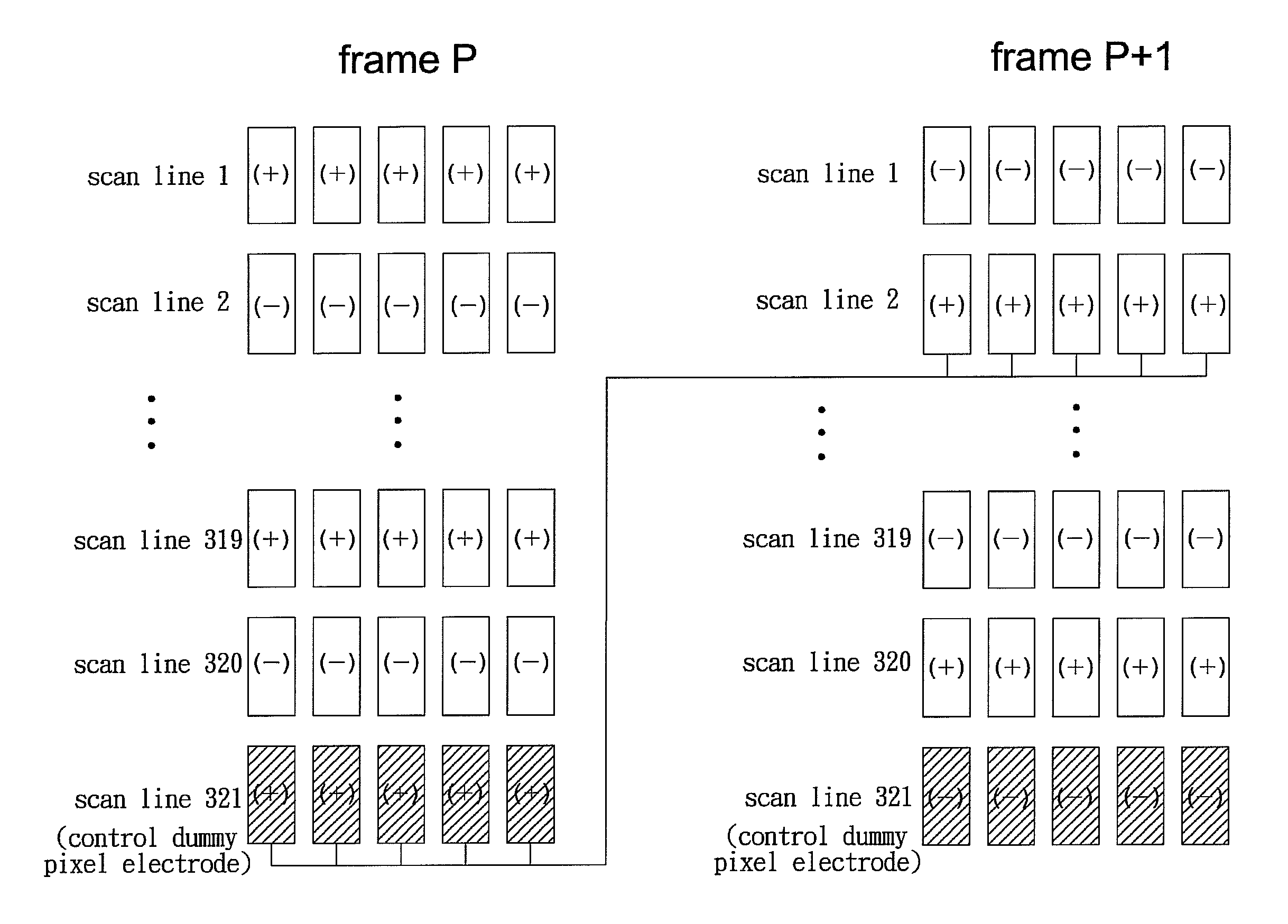
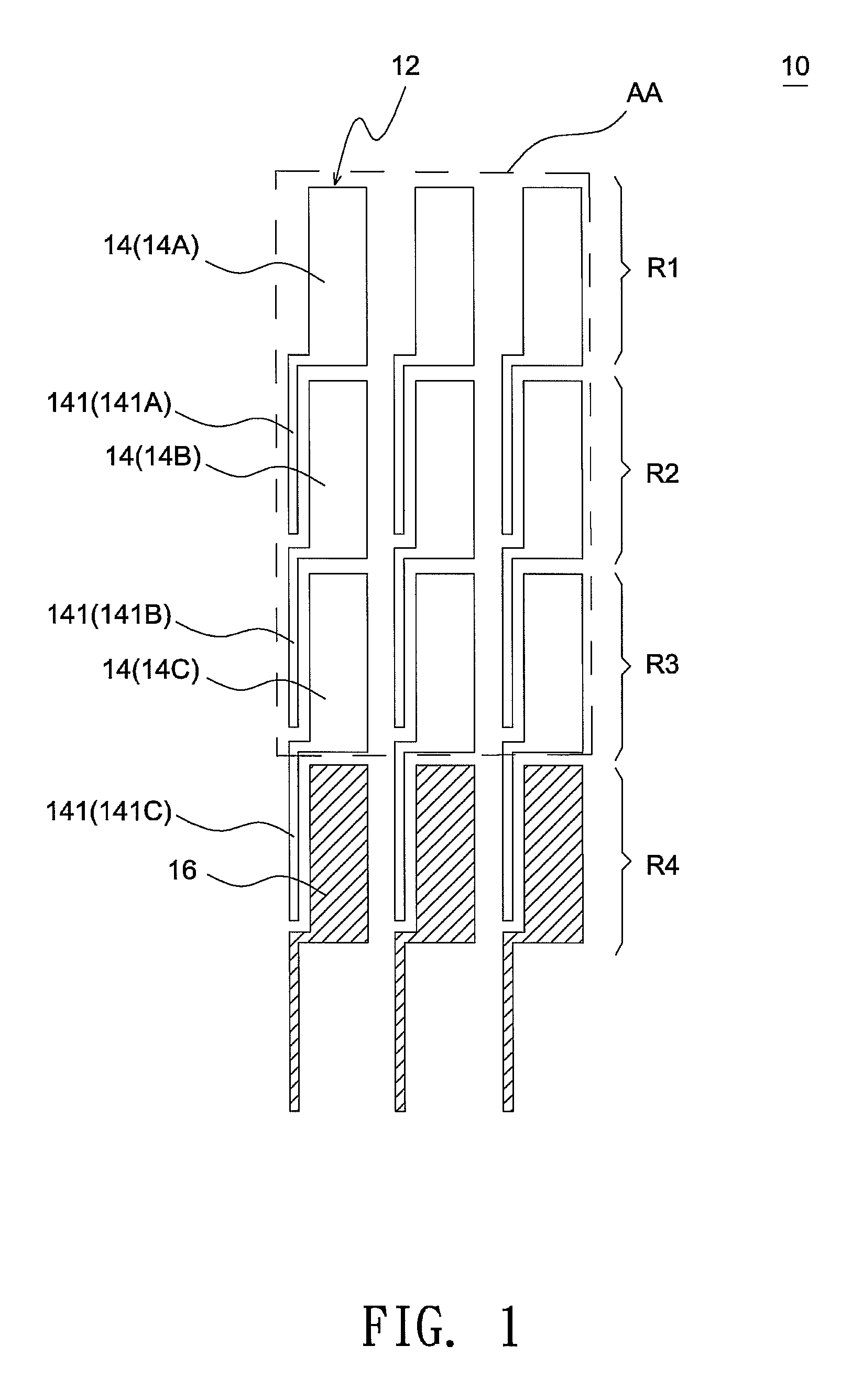
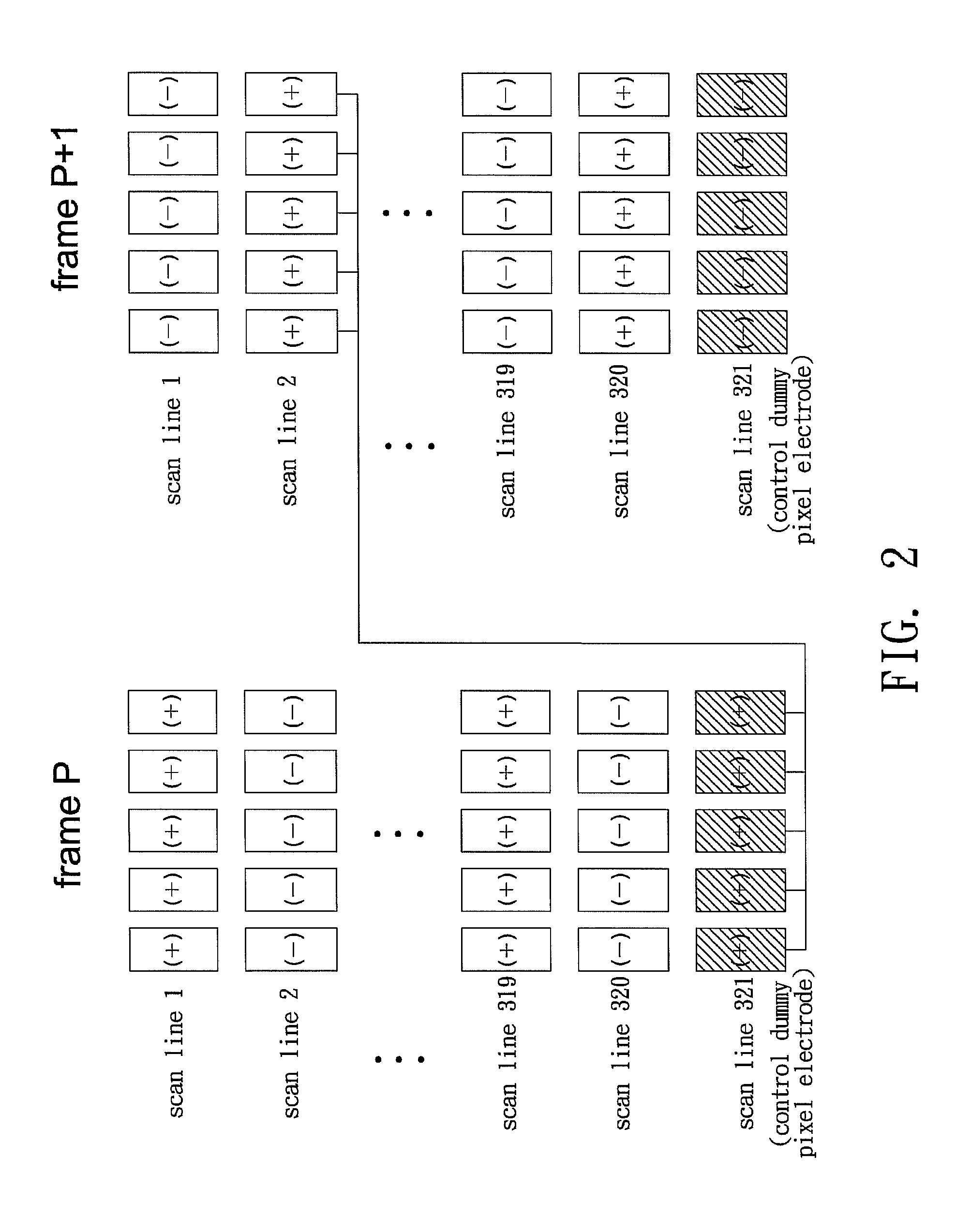
[0012]According to the above embodiments, a multi-domain profile of a LC cell can be easily achieved through typical TFT fabrication processes. Hence, compared with the conventional design where a protrusion or concave structure is used to cause tilted liquid crystal molecules, the residue phase difference is eliminated to avoid light leakage according to this embodiment since all liquid crystal molecules are vertically aligned under a field-off state. Further, compared with another conventional design where slits are formed to produce fringe fields, the biased auxiliary electrodes allow for stronger field strength to tilt liquid crystal molecules so as to reduce the areas of a disclination region and thus increase the light-transmittance of an LCD. Further, under the design that auxiliary electrodes are used to produce fringe fields, that dummy pixel electrodes arranged adjacent to the side of active display area and coupled to gate signals may allow each effective pixel electrode to have the same coupling capacitance, thus ensuring identical luminance for all pixels at a given gray-level.

Problems solved by technology

However, the strength of the fringe fields generated by the formation of the slits 206 is often insufficient, particularly when the widths and the intervals of the slits 206 are not optimized.

Method used


Image

  • Multi-domain liquid crystal display
  • Multi-domain liquid crystal display
  • Multi-domain liquid crystal display

Examples


Embodiment Construction

[0027]In the following detailed description of the preferred embodiments, reference is made to the accompanying drawings which form a part hereof, and in which is shown by way of illustration specific embodiments in which the invention may be practiced. In this regard, directional terminology is used with reference to the orientation of the Figure(s) being described. The components of the present invention can be positioned in a number of different orientations. As such, the directional terminology is used for purposes of illustration and is in no way limiting. On the other hand, the drawings are only schematic and the sizes of components may be exaggerated for clarity. It is to be understood that other embodiments may be utilized and structural changes may be made without departing from the scope of the present invention. Also, it is to be understood that the phraseology and terminology used herein are for the purpose of description and should not be regarded as limiting. The use o...


PUM

PropertyMeasurementUnit
areaaaaaaaaaaa
coupling capacitanceaaaaaaaaaa
response speedaaaaaaaaaa

Abstract

A multi-domain liquid crystal display (LCD) includes multiple effective pixel electrodes, dummy pixel electrodes and auxiliary electrodes. The effective pixel electrodes are regularly arranged in an array of row and column, and the array of effective pixel electrodes constitute an active display area of the multi-domain LCD. The dummy pixel electrodes are provided outside the active display area and arranged at least on the side of an outermost row or outermost column of the array of effective pixel electrodes. Each auxiliary electrode is positioned next to one side of an effective pixel electrode or a dummy pixel electrode to produce fringe fields and is connected to another effective pixel electrode controlled by a preceding or a succeeding signal line to allow all effective pixel electrodes to have substantially the same coupling capacitance.

Description

CROSS REFERENCE TO RELATED APPLICATION[0001]This application claims priority of application No. 096134785 filed in Taiwan R.O.C on Sep. 19, 2007 under 35 U.S.C. §119; the entire contents of which are hereby incorporated by reference.BACKGROUND OF THE INVENTION[0002]1. Field of the Invention[0003]The invention relates to a multi-domain liquid crystal display having excellent luminous uniformity.[0004]2. Description of the Related Art[0005]Typically, the display contrast ratio and response speed offered by a VA (vertically-aligned) mode liquid crystal display, which uses negative liquid crystal materials and vertical alignment films, are better than a TN (twisted-nematic) mode LCD, since liquid crystal molecules are aligned in a vertical direction when no voltage is applied. Also, it is known the viewing angle performance of a VA mode LCD is improved by setting the orientation directions of the liquid crystal molecules inside each picture element to a plurality of mutually different d...

Claims


Application Information

Patent Timeline
Patent Type & Authority Patents(United States)
IPC IPC(8): G02F1/1343
CPCG02F1/134309G02F2001/134345G02F2201/122G09G3/3614G09G2300/0426G09G2320/0209G09G2320/0233G02F1/134345
Inventor WANG, WEN-CHUNWANG, I-FANGYU, MING-CHANGTSAI, YING-CHENG
Owner WINTEK CORP
Why Eureka
Eureka Blog
Learn More