Wavelength routing system
a routing system and wavelength technology, applied in the field of wavelength routing technique, can solve the problems of difficult to deal with communication congestion and difficulty in enlarging the transmission band among the nodes
- Summary
- Abstract
- Description
- Claims
- Application Information
AI Technical Summary
Benefits of technology
Problems solved by technology
Method used
Image

Examples
first embodiment
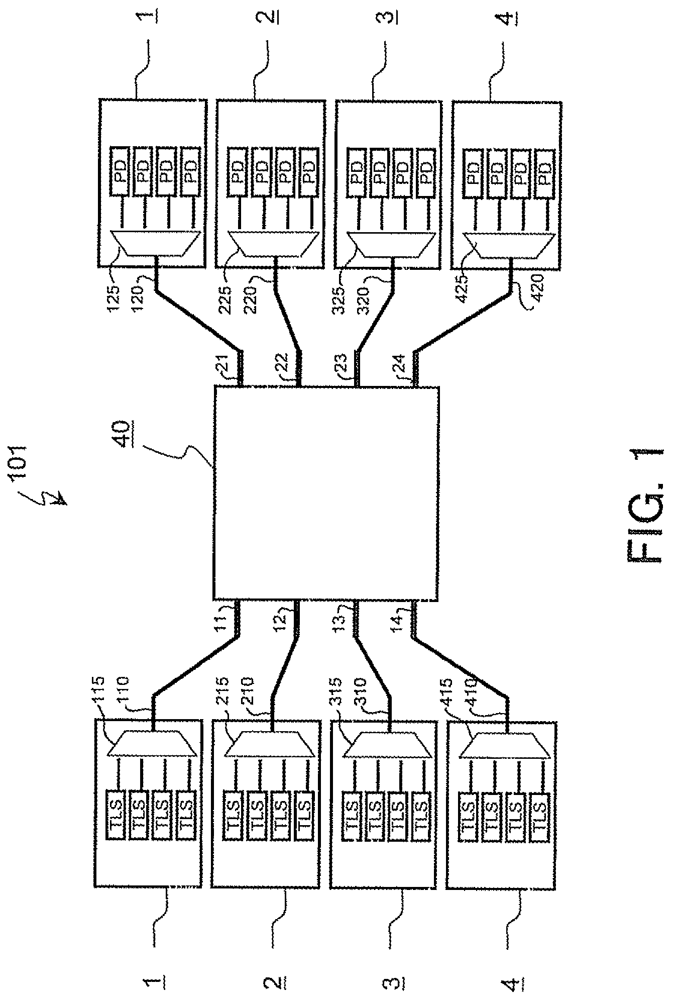
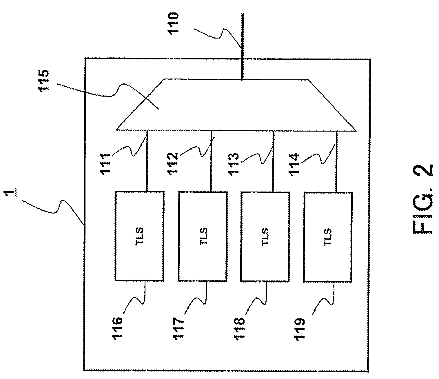
[0069]Embodiments of the present invention will be described with reference to the drawings in detail. FIG. 1 shows a configuration of a system according to a first embodiment of the present invention. A system 101 according to this embodiment is a system in which four nodes are connected to an array waveguide grating 40 having a routing property. Output ports 110, 210, 310 and 410 of nodes 1 to 4 are connected to input ports 11 to 14 of the array waveguide grating 40, respectively. Further, input ports 120, 220, 320 and 420 of the nodes 1 to 4 are connected to output ports 21 to 24 of the array waveguide grating 40, respectively. For convenience of description, FIG. 1 shows that each of the nodes 1 to 4 is divided into an optical transmitter (a left side) and an optical receiver (a right side). However, there is no need to divide each of the nodes 1 to 4 in an actual hardware configuration.
[0070]FIG. 2 shows a configuration of the optical transmitter of the node 1. The optical tran...
second embodiment
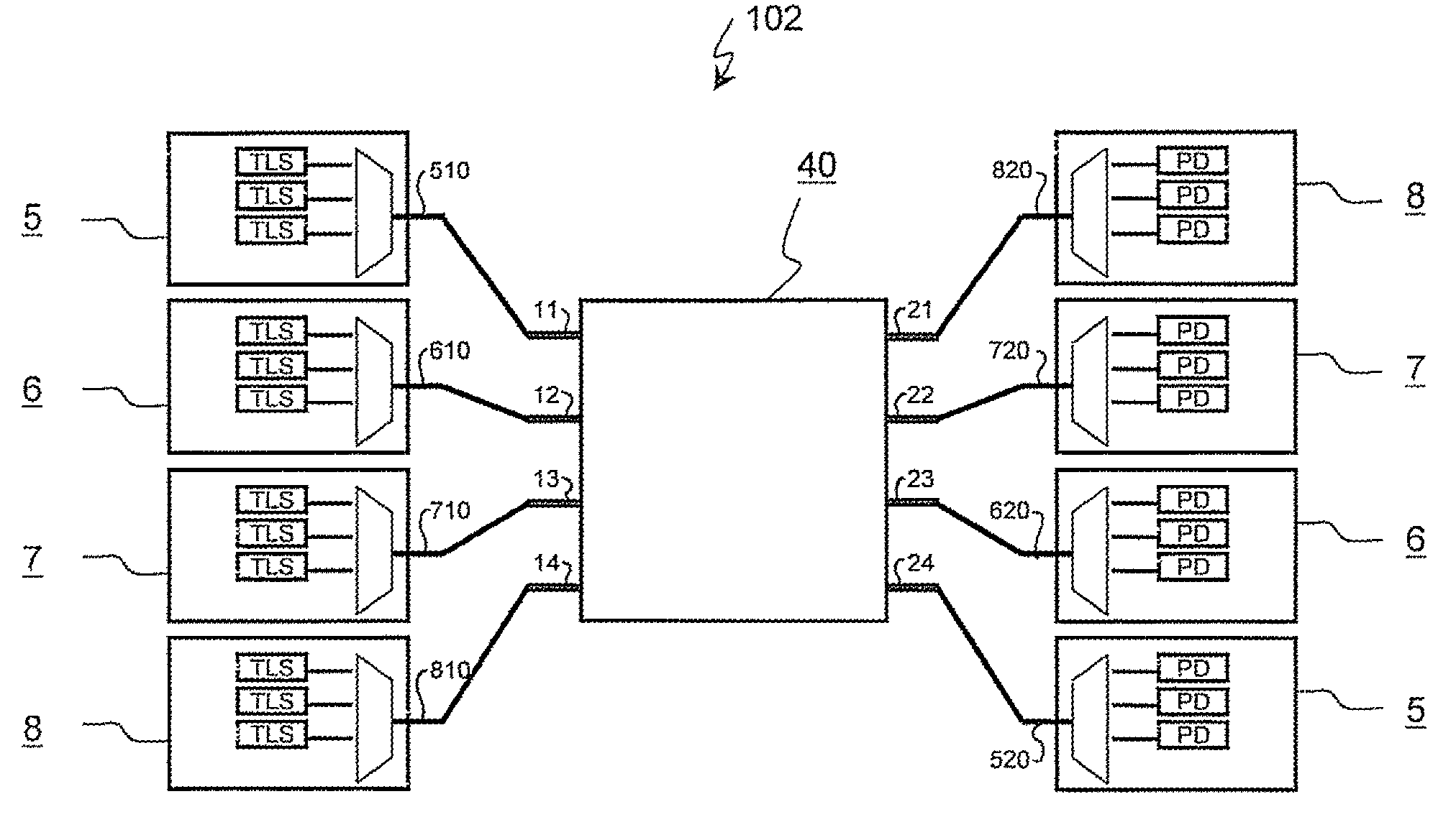
[0107]FIG. 13 shows a configuration of a system according to a second embodiment of the present invention. While each of the number of tunable wavelength light sources (TLS) and that of the photodetectors (PD) provided in each node is “4” in the system 101 shown in FIG. 1, each of the numbers is “3” in a system 102 according to this embodiment.
[0108]In the system 102, output ports 510, 610, 710 and 810 of four nodes 5 to 8 are connected to input ports 11 to 14 of an array waveguide grating 40, respectively. On the other hand, input ports 520, 620, 720 and 820 of the nodes 5 to 8 are connected to output ports 24, 23, 22 and 21 of the array waveguide grating 40, respectively. That is, as obvious from comparison of left and right in FIG. 13, an optical transmitter and an optical receiver of each of the nodes 5 to 8 are connected to each other in reverse.
[0109]FIG. 14 shows a configuration of the optical transmitter (a left side in FIG. 13) of the node 5. In the optical transmitter, thr...
third embodiment
[0127]FIG. 23 shows a configuration of a system according to a third embodiment of the present invention. A system 103 according to this embodiment is configured to double connection paths among four nodes 50 to 80 so as to change over to preliminary connection paths if normal connection paths become unavailable. As shown in FIG. 23, the system 103 according to this embodiment includes not only a normal array waveguide grating 40 but also a preliminary array waveguide grating 90 having a routing property similarly to the normal array waveguide grating 40.
[0128]Output ports 5010, 6010, 7010 and 8010 of nodes 50 to 80 are connected to input ports 11 to 14 of the normal array waveguide grating 40, respectively. Input ports 5020, 6020, 7020 and 8020 of the nodes 50 to 80 are connected to output ports 21 to 24 of the array waveguide grating 40, respectively. Furthermore, different output ports 5030, 6030, 7030 and 8030 of the nodes 50 to 80 are connected to input ports 61 to 64 of the pr...
PUM
 Abstract
Description
Claims
Application Information
 - R&D
- Intellectual Property
- Life Sciences
- Materials
- Tech Scout
- Unparalleled Data Quality
- Higher Quality Content
- 60% Fewer Hallucinations
Browse by: Latest US Patents, China's latest patents, Technical Efficacy Thesaurus, Application Domain, Technology Topic, Popular Technical Reports.
© 2025 PatSnap. All rights reserved.Legal|Privacy policy|Modern Slavery Act Transparency Statement|Sitemap|About US| Contact US: help@patsnap.com