
Method and apparatus for correcting errors in a multiple subcarriers communication system using multiple antennas

a communication system and multiple antenna technology, applied in the field of multiple antenna system correction, can solve the problems of reducing the speed of change, limiting the several problems of the above-mentioned time-space symbol based harq, so as to improve the speed and reliability of data transmission, reduce the spatial multiplexing rate, and improve the effect of speed and reliability

Active Publication Date: 2012-11-13
LG ELECTRONICS INC
View PDF25 Cites 16 Cited by
  • Summary
  • Abstract
  • Description
  • Claims
  • Application Information

AI Technical Summary

Benefits of technology

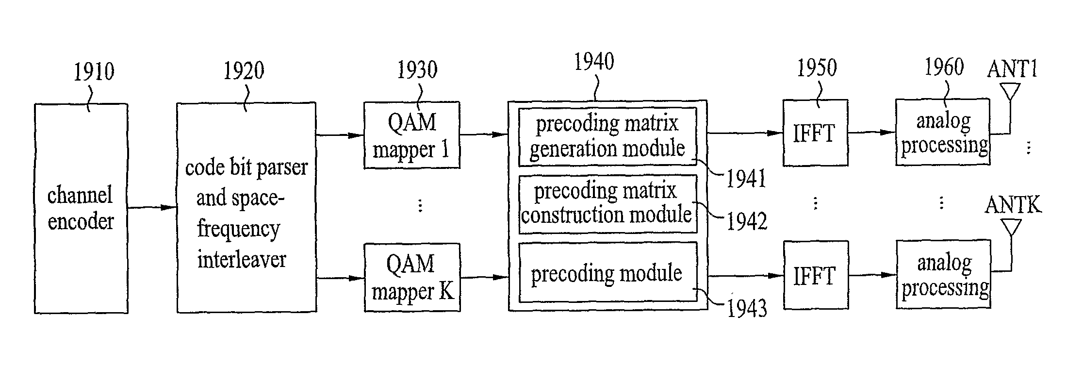
The present invention provides a method and apparatus for correcting errors in a multiple antenna system based on a plurality of sub-carriers. The method involves determining a precoding matrix with a phase shift, transmitting each sub-carrier symbol using the precoding matrix, and retransmitting if a negative reception acknowledgement is received. The apparatus includes a preceding matrix determination module, an offset application module, and a preceding module. The technical effects of the invention include improved speed and reliability in data transmission, simultaneous improvement in speed and reliability, and improved overall performance of the multiple antenna system.

Problems solved by technology

However, the aforementioned time-space symbol based HARQ has several problems.
First, the time-space symbol based HARQ has limitation in that it is based on a flat fading channel whose change speed is relatively slow.
Second, if multiple codewords are used, it is inefficient in that retransmission of all codewords is required even though errors occur only in some of the codewords.
Third, flexibility is deteriorated in that initial transmission should be performed by a spatial multiplexing scheme such as BLAST.
Finally, since the adaptive ARQ such as incremental redundancy cannot be used for the time-space based HARQ, efficient error correction cannot be performed.

Method used


Image

  • Method and apparatus for correcting errors in a multiple subcarriers communication system using multiple antennas
  • Method and apparatus for correcting errors in a multiple subcarriers communication system using multiple antennas
  • Method and apparatus for correcting errors in a multiple subcarriers communication system using multiple antennas

Examples


first embodiment

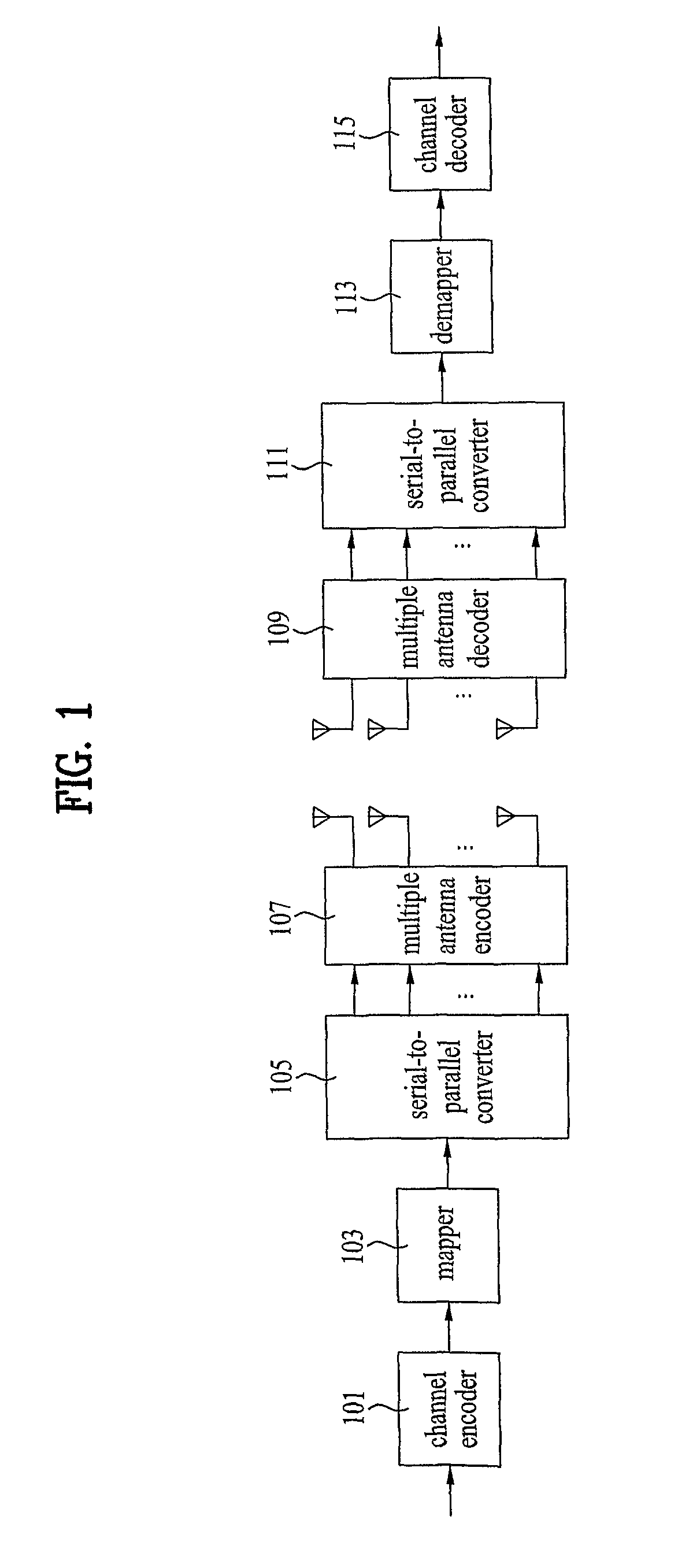
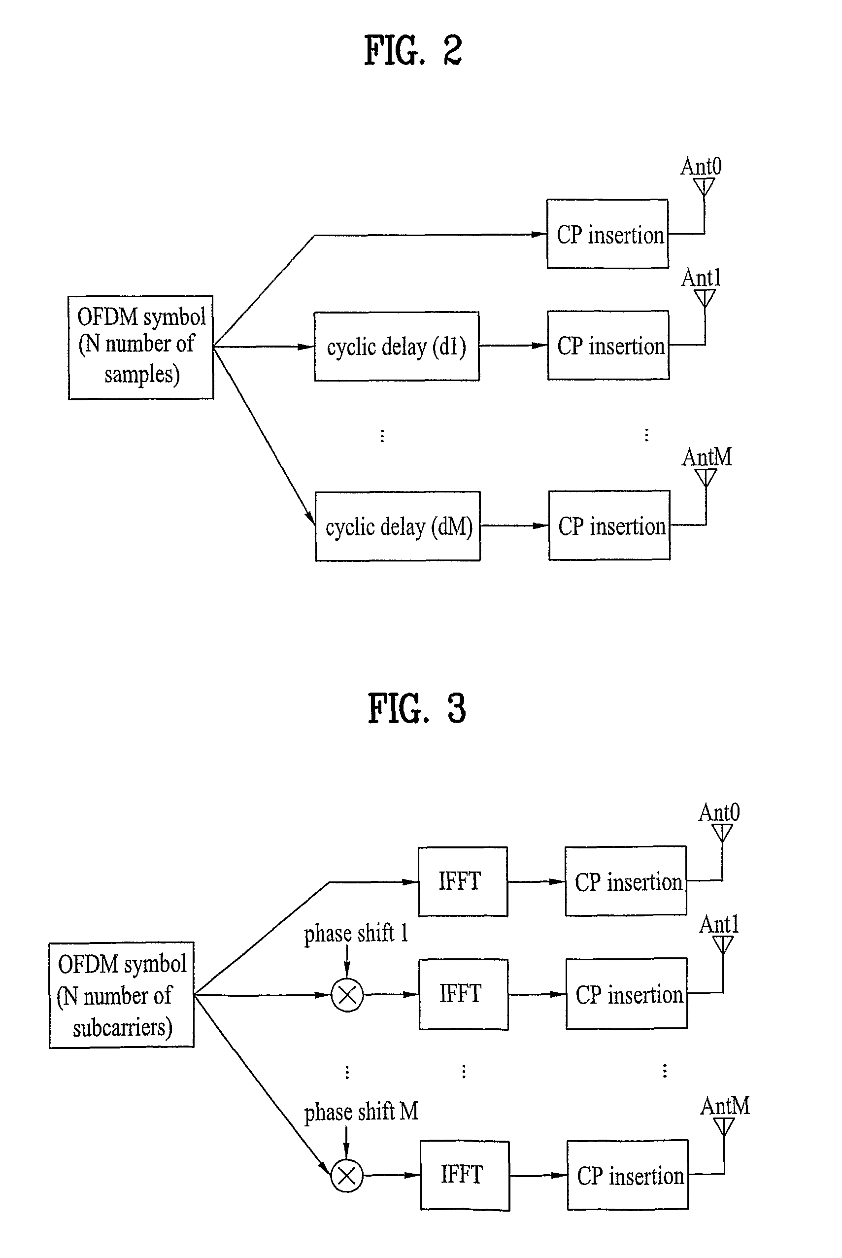
[0060]As described above, cyclic delay diversity or phase shift diversity is advantageous in that it can be applied to both an open loop system and a closed loop system depending on a cyclic delay value and can simply be implemented. However, a problem occurs in that a data transmission rate is reduced due to a spatial multiplexing rate of 1. Also, although codebook based preceding is advantageous in that efficient data transmission can be performed by feedback of index, problems occur in that the codebook based precoding is not suitable for a mobile environment in which channel change is frequent and that memory use increases as a codebook should be provided at both sides of a transmitter / receiver. Accordingly, the present invention suggests a phase shift based preceding method, which can easily change precoding matrixes depending on circumstances and has advantages of phase shift diversity and preceding, and a method for correcting errors, which includes ARQ scheme.

[0061]Hereinaft...

second embodiment

[0144]In the aforementioned first method, a corresponding precoding matrix is changed such that phase value offset and / or sub-carrier index offset information, which is fed back from the receiver or randomly set in the transmitter, is applied to the phase shift based precoding matrix before reconstruction to lower the spatial multiplexing rate, whereby a preceding matrix optimized for retransmission can be obtained. Hereinafter, the procedure of changing the preceding matrix by allowing the system having four antennas and a spatial multiplexing rate of 2 to apply phase value offset and / or sub-carrier index offset to the phase shift based precoding matrix in Table 2 will be described in accordance with embodiments. In this case, it will be apparent to those with ordinary skill in the art to which the present invention pertains that the improved phase shift based precoding method of the present invention is not limited to the following embodiments and is applicable to a system having ...

first feedback embodiment

[0145]In this embodiment, as shown in FIG. 21A, sub-carrier index offset Noffset is fed back from the receiver and then applied to the phase shift based preceding matrix.

[0146]As shown in FIG. 21B, it is noted that a channel area (area allocated for a solid line sine wave) initially allocated to sub-carrier of index k is relatively poorer than the other areas. Accordingly, the receiver checks the channel status of the resource allocated to the corresponding sub-carrier, sets a proper offset Noffset, and feeds back the set offset Noffset to the transmitter. The transmitter applies the fed-back offset Noffset to the existing phase shift based preceding matrix so that the corresponding sub-carrier moves to the optimized channel area (area allocated for a dotted line sine wave). An equation of the phase shift based precoding matrix to which the fed-back index offset Noffset has been applied can be expressed as follows.

[0147]14⁢(1-ⅇ-j⁢⁢θ1⁡(k+Noffset)ⅇj⁢⁢θ1⁡(k+Noffset)1ⅇj⁢⁢θ2⁡(k+Noffset)-...


PUM


Abstract

A method for correcting errors in a multiple antenna system based on a plurality of sub-carriers and a transmitting / receiving apparatus supporting the same are disclosed. The method includes determining a phase shift based precoding matrix phase shifted at a predetermined phase angle, initially transmitting each sub-carrier symbol to a receiver in a packet unit by using the phase shift based precoding matrix, reconstructing the phase shift based precoding matrix to reduce a spatial multiplexing rate if a negative reception acknowledgement (NACK) is received from the receiver, and retransmitting the initially transmitted sub-carrier symbol by using the reconstructed phase shift based precoding matrix or by changing the phase shift based precoding matrix using offset information fed back from the receiver or random offset information.

Description

CROSS-REFERENCE TO RELATED APPLICATIONS[0001]This Application is the National Stage filing under 35 U.S.C. §371 of International Application No. PCT / KR2007 / 003295, filed on Jul. 6, 2007, which claims the benefit of earlier filing date and right of priority to Korean Application No. 10-2006-0091278, filed on Sep. 20, 2006, and also claims the benefit of U.S. Provisional Application Ser. No. 60 / 806,696, filed on Jul. 6, 2006.TECHNICAL FIELD[0002]The present invention relates to a method for correcting errors in a multiple antenna system based on a plurality of sub-carriers to perform an automatic repeat request scheme, and a transmitting and receiving apparatus supporting the same.BACKGROUND ART[0003]Recently, as information communication services have been popularized, a variety of multimedia services has appeared, and high-quality services have appeared, a demand for a wireless communication service is rapidly increasing. In order to actively cope with such a tendency, it is necessa...

Claims


Application Information

Patent Timeline
Patent Type & Authority Patents(United States)
IPC IPC(8): G08C25/02
CPCH04B7/0639H04B7/0656H04L1/0025H04B7/0456H04L1/1893H04B7/0417H04L1/0625H04L27/2601H04B7/005H04L1/02H04B7/0697H04L1/1819
Inventor LEE, MOON ILIHM, BIN CHULCHUN, JIN YOUNG
Owner LG ELECTRONICS INC
Learn More