Valve incorporating means for balancing pressures on either side of a valve member

a valve and valve body technology, applied in the direction of lifting valves, functional valve types, non-fuel substance addition to fuel, etc., can solve the problems of sacrificing effectiveness, presenting relatively large size and relatively high electricity consumption, and lengthening the duration and complexity of assembly, etc., to achieve the effect of sacrificing effectiveness

Inactive Publication Date: 2012-11-13
VALEO SYST DE CONTROLE MOTEUR
View PDF6 Cites 7 Cited by
  • Summary
  • Abstract
  • Description
  • Claims
  • Application Information

AI Technical Summary

Benefits of technology

[0007]Thus, the diaphragm co-operates with the support element to form a chamber at the same pressure as the outlet chamber, thus making it possible to limit the force that needs to be exerted on the valve member in order to bring it into its open position. The substantially plane shape of the diaphragm makes it possible for the valve to be compact in structure. In addition, the resilient return of the valve member into the closed position is provided by the diaphragm itself, so there is no need to add a spring dedicated to providing this effect. In order to perform these functions, the diaphragm is relatively stiff, thus also enabling it to guide the valve member. Another advantage of using a resilient return diaphragm lies in the fact that during movement of the valve member towards its open position, the force exerted by the diaphragm increases rapidly and tends to slow the valve member down as it arrives in the open position. This helps limit the noise made by the valve in operation. Such a diaphragm is made of materials that are relatively stiff, and in particular of metals that present relatively good ability to withstand fuel at lesser cost.

Problems solved by technology

This requires an electromagnetic member that is dimensioned accordingly, thereby presenting relatively large size and relatively high levels of electricity consumption.
As a result the valve has a relatively large number of parts, thereby lengthening the duration and the complexity of assembly.
In addition, assembling the sleeve and the spring is quite difficult.
Furthermore, given the shape of the sleeve and the deformation to which it is subjected, the sleeve is made of an elastomer, which presents only limited ability to withstand fuel, unless it is prohibitively expensive.

Method used


Image

  • Valve incorporating means for balancing pressures on either side of a valve member
  • Valve incorporating means for balancing pressures on either side of a valve member

Examples


Embodiment Construction

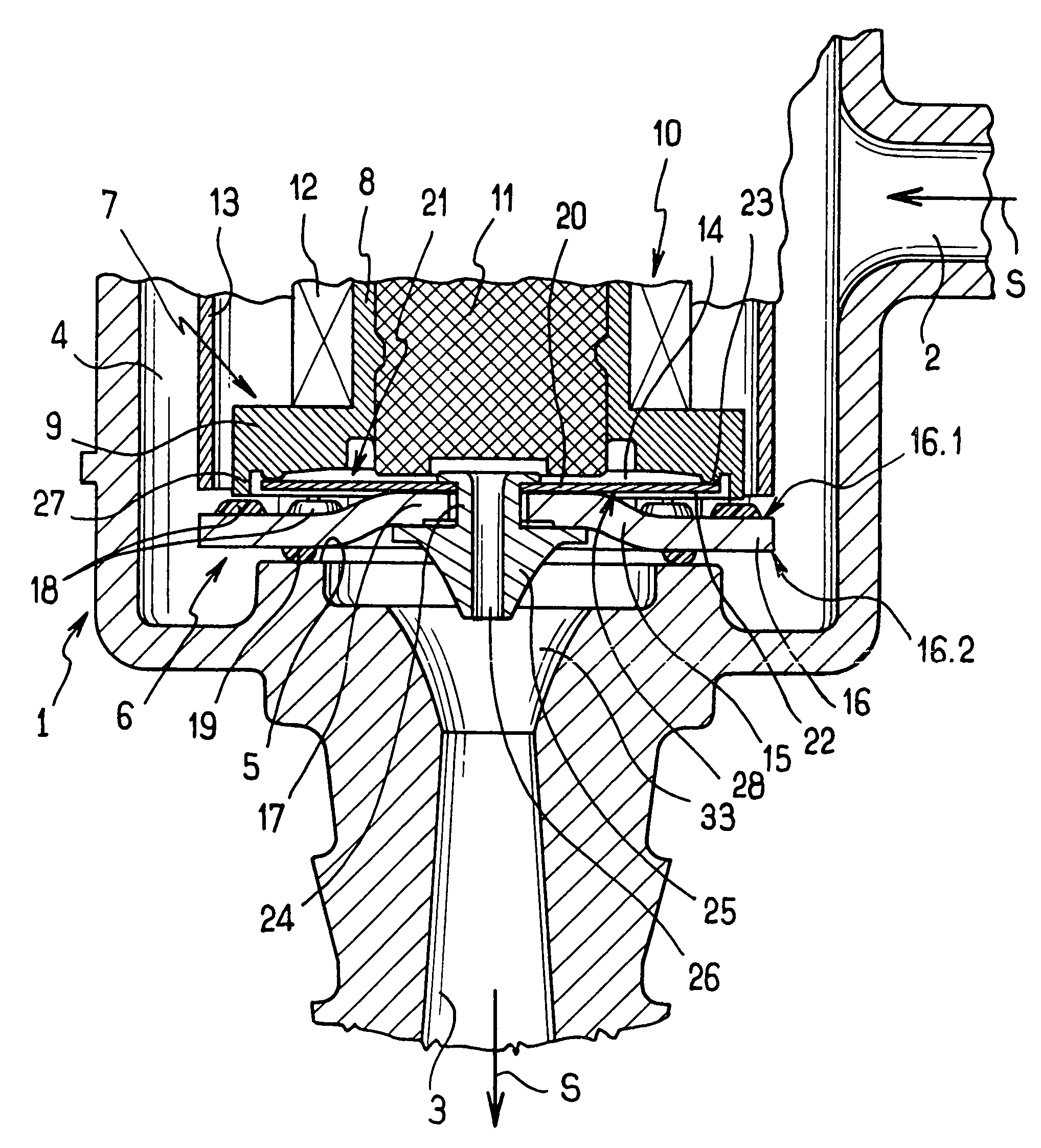
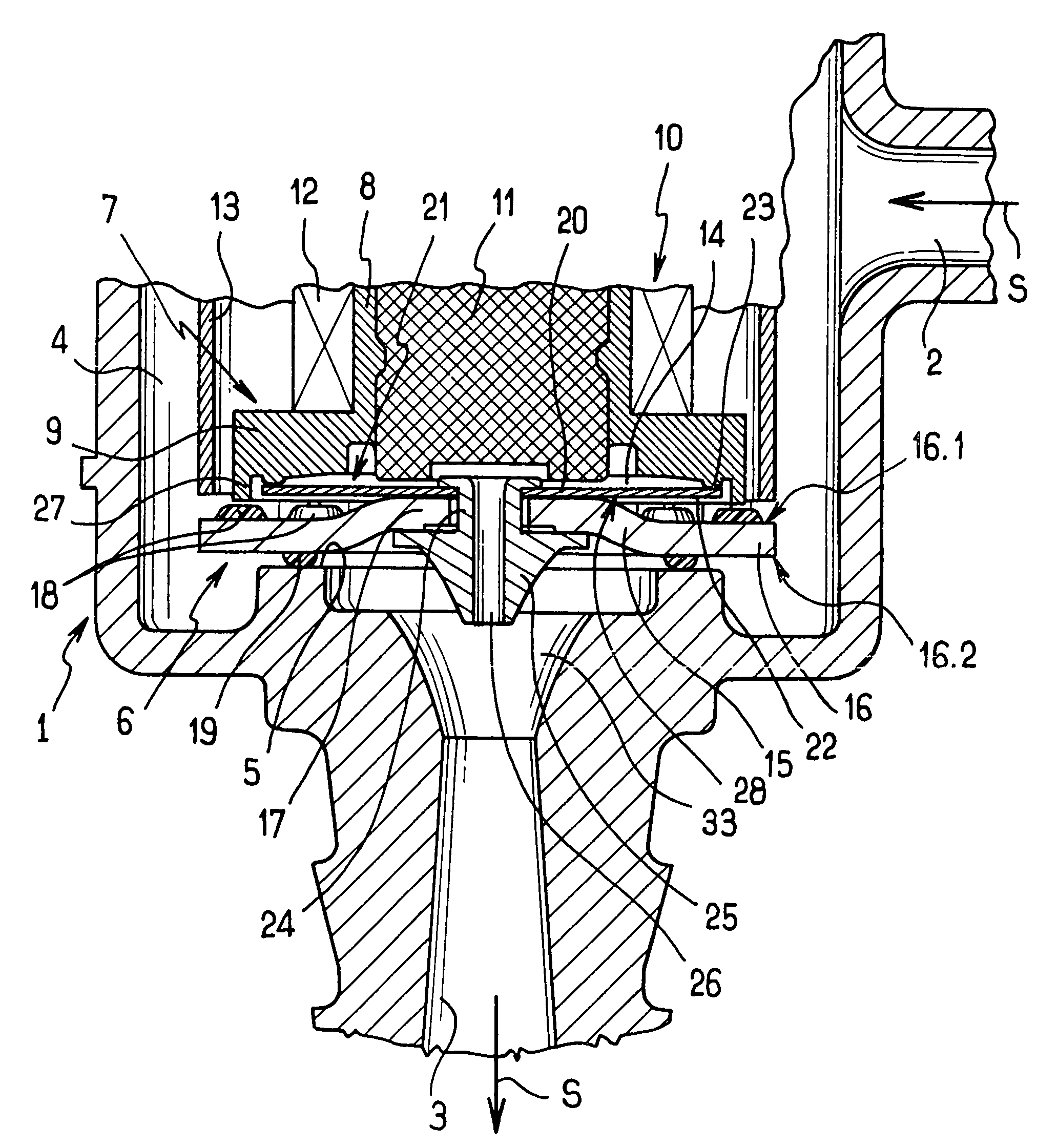
[0010]With reference to the FIGURE, the valve in accordance with the invention comprises a body given overall reference 1, defining an admission duct 2 and an outlet duct 3, each having one end that opens out into a housing 4 of the body 1. The outlet duct 3 is shaped to have a segment 33 that converges (relative to the fluid flow direction represented by arrows S) in the vicinity of said end. The end is surrounded in the housing 4 by a seat 5 against which there bears a valve member given overall reference 6 that is associated, in a manner described in greater detail below, with a support element given overall reference 7 that is secured to the body 1 so as to extend inside the housing 4 in line with the outlet duct 3.

[0011]The support element 7 has a tubular portion 8 with one end adjacent to the seat 5 that is terminated by a collar 9. The support element 7 is made of a non-magnetic material.

[0012]An electromagnetic actuator member 10 of known type is mounted on the support eleme...


PUM


Abstract

The disclosure relates to a valve comprising a body defining at least an admission duct and an outlet duct for a fluid and receiving a valve member that is movable by means of an actuator member fastened to the body to move between a closed position closing the outlet duct and an open position leaving it open, the valve member having a central portion secured to a central portion of a substantially plane diaphragm that has a peripheral portion associated in leaktight manner with a support element secured to the body in such a manner as to co-operate with the support element to define a chamber, the valve member and the diaphragm being pierced by an opening providing permanent communication between the chamber and the outlet duct, the diaphragm being elastically deformable and being dimensioned to urge the valve member into its closed position.

Description

[0001]The present invention relates to a valve suitable for use in particular for controlling the flow rate of a fluid in a fluid transport circuit, such as the circuit feeding a motor vehicle engine with fuel, for example.BACKGROUND OF THE INVENTION[0002]Such a valve generally comprises a body defining an inlet duct and an outlet duct for a fluid and receiving a valve member that is movable between a closed position in which it closes the outlet duct and an open position in which it is spaced apart therefrom by means of an actuator member fastened to a support element secured to the body. By way of example, the actuator member is an electromagnetic actuator member associated with a spring for returning the valve member into its closed position.[0003]When the valve member is in the closed position, the pressure acting on the valve member beside the inlet duct differs from the pressure acting on the valve member beside the outlet duct. The force that results from this pressure differ...

Claims


Application Information

Patent Timeline
Patent Type & Authority Patents(United States)
IPC IPC(8): F16K31/02
CPCF16K31/0655F16K31/0693F02M2025/0845
Inventor VAZ DE AZEVEDO, JOSE
Owner VALEO SYST DE CONTROLE MOTEUR
Why Eureka
Try Eureka