
Wheel chock system

a technology of wheel chocks and icc bars, which is applied in the field of restraining vehicles, can solve the problems of wheel chocks that slip out of position on slippery driveways, not all trucks have an icc bar that can be readily accessible, and the problem of getting misplaced

Active Publication Date: 2012-11-13
RITE HITE HLDG CORP
View PDF136 Cites 41 Cited by
  • Summary
  • Abstract
  • Description
  • Claims
  • Application Information

AI Technical Summary

Benefits of technology

The patent describes various embodiments of a wheel chock that can be used to restrain a vehicle at a loading dock. The chock is supported by an articulated arm that can be locked in place to prevent the chock from moving. The chock can also have a sensor to detect if it is fully engaged with the vehicle's wheel. Additionally, the patent describes a hydraulic cylinder that can force the chock against the vehicle's wheel using a manually manipulated wheel chock. The patent also mentions the use of hooks or latches to engage and release the chock from the ground, as well as a cleaning system to prevent debris and other contaminants from accumulating on the surface where the chock is placed. Overall, the patent provides various technical solutions for safely and securely restraining vehicles at loading docks.

Problems solved by technology

However, not all trucks have an ICC bar that can be readily engaged by an ICC-style restraint.
However, wheel chocks often slip out of position on driveways that are slippery due to oil, rain, ice, sand, gravel or dirt.
Moreover, wheel chocks usually are loose items that do not permanently attach to the loading dock area, so they often get misplaced.
First, a counterweight spring on the arm tends to prevent the wheel chock from resting its full weight upon the base plate.
Second, the length to which the arm must extend to reach the wheel can adversely affect the angular relationship (about a vertical axis) between the mating surfaces of the chock and base plate.
Third, although the '720 device includes a sensor for detecting the presence of a wheel, the sensor does not indicate whether the chock is fully engaged with the serrations of the base plate. And fourth, dirt, ice and other contaminants could hinder the engagement between the chock and the base plate, thus reducing the effectiveness of the chock.

Method used


Image

  • Wheel chock system
  • Wheel chock system
  • Wheel chock system

Examples


Embodiment Construction

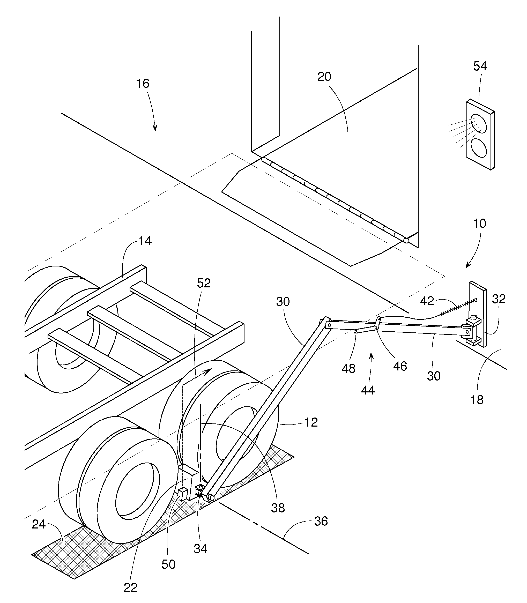
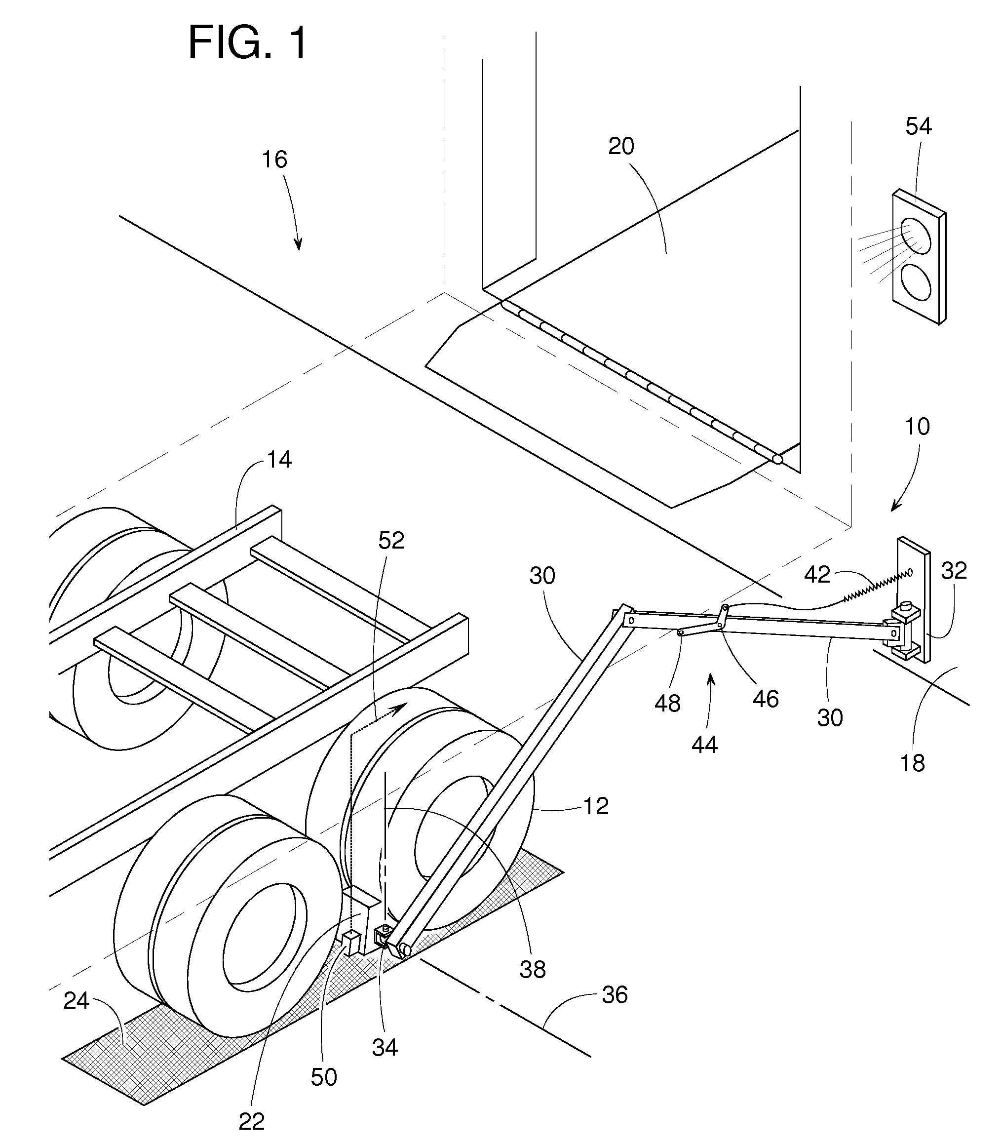
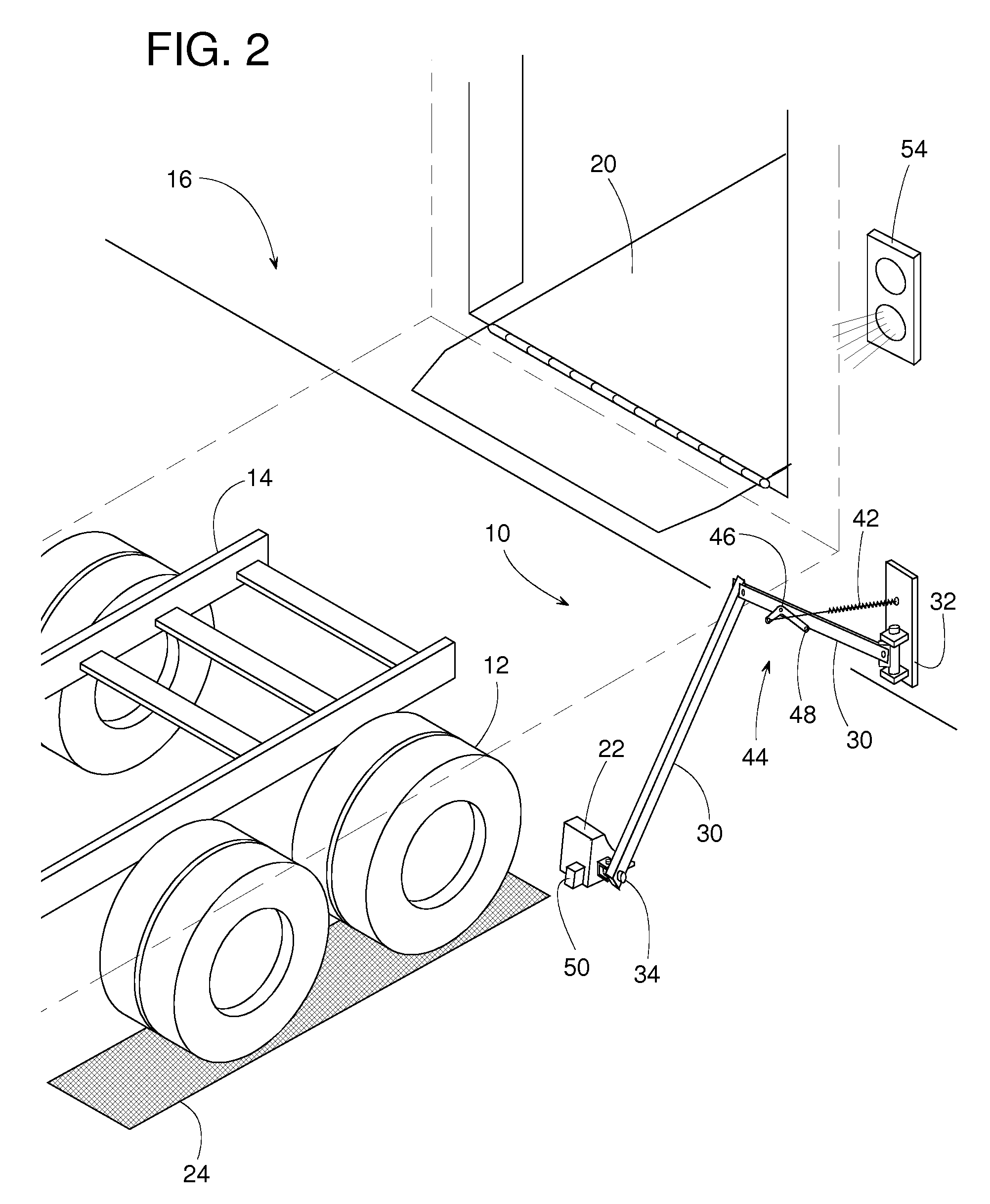
[0029]FIGS. 1 and 2 show a wheel restraint system 10 for restraining at least one wheel 12 of a vehicle 14 at a loading dock 16. Restraint 10 is shown in a holding position in FIG. 1 and is shown in a release position in FIG. 2. In the holding position, restraint 10 helps hold vehicle 14 adjacent to a dock face 18 so that cargo can be safely conveyed on and off of vehicle 14. In some cases, a conventional dock leveler 20 can be used to facilitate the loading and unloading operations. An upper section of vehicle 14 is shown in phantom lines to more clearly show the subject invention.

[0030]Wheel restraint 10 includes a wheel chock 22 that may, for example, rest upon a base 24 (lower support surface) when restraint 10 is in the holding position of FIG. 1. To limit the wheel chock's horizontal movement (particularly in a forward direction away from dock face 18) base 24 and / or chock 22 may include an interlocking feature such as a tooth 26 or 28 that engages a mating feature in the oppo...


PUM


Abstract

A wheel restraint for restraining a vehicle at a loading dock includes various features such as, a wheel chock supported by a spring loaded articulated arm with a spring that can be selectively tightened or released, a sensor that detects whether the chock is solidly against a base plate or floor, a bi-directional pivotal joint between the articulated arm and the wheel chock to ensure that the chock can sit squarely on a mating base plate, a wheel chock that meshes with a hydraulically actuated base plate, pivotal or otherwise movable backstops that prevent a wheel chock from sliding out of position, and a base plate cleaning system. The cleaning system might include a vehicle-actuated brush, fluid spray nozzles, electric heater and removable cover plates.

Description

FIELD OF THE DISCLOSURE[0001]The present disclosure generally pertains to restraining a vehicle at a loading dock and more specifically to a wheel chock system.BACKGROUND OF RELATED ART[0002]When a truck, trailer or some other vehicle is parked at a loading dock, often some sort of vehicle restraint is used to keep the truck from inadvertently moving away from an elevated platform of the dock. This allows a forklift truck to safely drive between the dock platform and the truck for the purpose of loading or unloading the cargo inside the truck.[0003]There are a variety of vehicle restraints available that can be installed at a loading dock for engaging the truck's RIG (Rear Impact Guard), also known as an ICC bar. An ICC bar is a beam that extends horizontally across the rear of a truck, just below the truck bed. Its primary purpose is to prevent an automobile from under-riding the truck in a rear-end collision. However, not all trucks have an ICC bar that can be readily engaged by a...

Claims


Application Information

Patent Timeline
Patent Type & Authority Patents(United States)
IPC IPC(8): B61H13/00
CPCB60T3/00B65G69/005
Inventor ANDERSEN, JONATHANBUBLITZ, ERICCOTTON, TIMOTHYKISH, JOHN A.LESSARD, KURTMUHL, TIMOTHYNELSON, KYLE E.PIETRANGELO, PAMELASANDER, REINHARD E.SVEUM, MATTWIEBERDINK, BENJAMIN
Owner RITE HITE HLDG CORP
Learn More