
Soundproof exhaust pipe for a turbine engine

a turbine engine and exhaust pipe technology, which is applied in the direction of machines/engines, combustion-air/fuel-air treatment, mechanical equipment, etc., can solve the problems of weight and bulk, noise from the turbine driving the blades becoming a substantial component of the total amount of sound emitted, etc., and achieves effective soundproofing

Inactive Publication Date: 2012-10-30
SAFRAN HELICOPTER ENGINES
View PDF21 Cites 0 Cited by
  • Summary
  • Abstract
  • Description
  • Claims
  • Application Information

AI Technical Summary

Benefits of technology

"The invention is a soundproofed exhaust duct for a turbine engine that provides effective soundproofing while having a relatively light structure. The exhaust duct comprises a perforated inner shell, a solid outer shell, a core containing at least one sound energy dissipating layer made up of hollow beads, and a frame that holds the core and is secured to the inner and outer shells. The frame is designed to accommodate dimensional variations between the outer shell and the frame. The exhaust duct also includes at least one solid partition that prevents noise propagating longitudinally in the spaces between the core and the inner and outer shells. The technical effects of the invention are effective soundproofing with a lightweight structure and the ability to accommodate dimensional variations."

Problems solved by technology

The progress that has been made in reducing the noise that is generated by the rotation of the rotor blades of a helicopter means that the noise from the turbine driving the blades is becoming a substantial component of the total amount of sound emitted.
The coating is relatively thick, given the sound frequencies concerned, thereby giving rise to problems of weight and of bulk.

Method used


Image

  • Soundproof exhaust pipe for a turbine engine
  • Soundproof exhaust pipe for a turbine engine
  • Soundproof exhaust pipe for a turbine engine

Examples


first embodiment

[0029]a soundproofed exhaust duct 10 of the invention is described with reference to FIGS. 1 to 5. The exhaust duct 10 shown is a nozzle of a gas turbine engine for a helicopter, and in known manner it presents a curved shape so as to ensure that the gas coming from the turbine is diverted in a direction away from the tail of the helicopter.

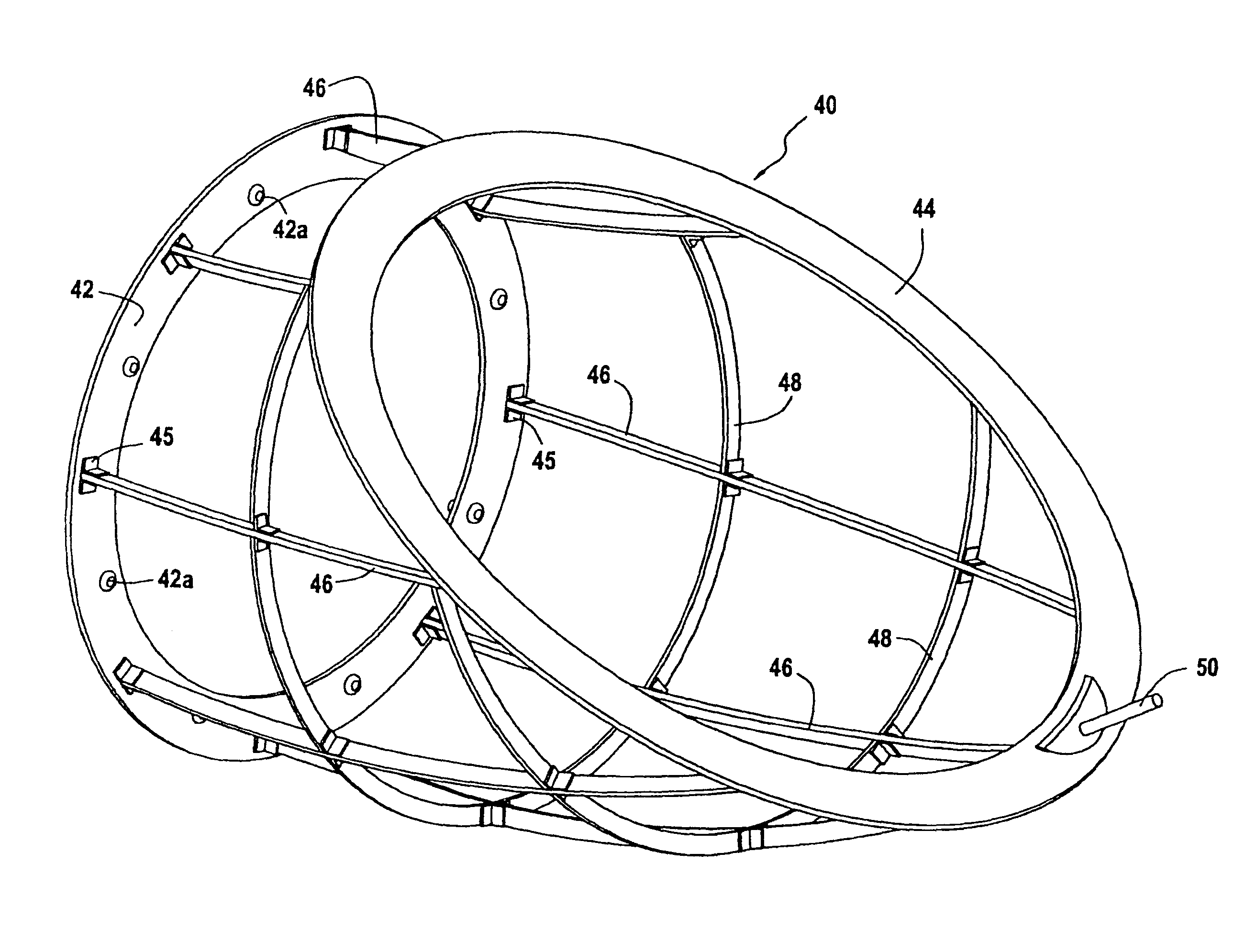
[0030]The duct 10 comprises a solid outer shell 20, a perforated inner shell 30 defining an exhaust passage 12 and spaced apart from the outer shell 20, a frame 40, and a sound energy dissipating core 60 that is supported and partitioned by the frame 40.

[0031]In this embodiment, the outer shell 20 performs the structural function of the exhaust duct. It may be made using metal sheet, for example using a nickel alloy, or it may be obtained by superplastic forming of a refractory titanium alloy. The shell 20 is made of two portions so as to enable the exhaust duct to be assembled: an upstream portion 20a and a downstream portion 20b that are fasten...

second embodiment

[0051]This second embodiment differs from that described above in that the structural function of the exhaust duct 110 is performed by the frame 140. The frame 140 is preferably made of a refractory metallic material, e.g. an alloy of nickel or titanium. In similar manner to the frame 40 of FIGS. 1 and 2, the frame 140 (FIGS. 7 and 8) has upstream and downstream rings 142 and 144 that are connected together by longitudinal members 146 that are themselves connected together by spacers 148, and the component portions of the frame are dimensioned so as to impart the desired structural role thereto.

[0052]The outer shell 120 comprises two portions, an upstream portion 120a and a downstream portion 120b. At its upstream end, the portion 120a is folded to form a radial portion 120c that is extended by an upstream terminal portion 120d that is pressed against the upstream terminal portion of the inner shell 130. At its downstream end, the portion 120b is folded to form a transverse portion ...


PUM


Abstract

The soundproofed exhaust duct for a turbine engine comprises a perforated inner shell defining a flow passage, and a solid outer shell, the inner and outer shells defining between them a space that is closed at the upstream and downstream ends of said space. A core extends between the inner and outer shells at a distance therefrom, and contains at least one sound energy dissipating layer made up of hollow beads that are held against one another. A frame with upstream and downstream portions connected together by longitudinal members supports the core and partitions it into a plurality of boxes that are filled with hollow beads that are held between perforated textures, the frame being secured to the outer shell and / or to the inner shell via at least one of its upstream and downstream portions.

Description

BACKGROUND OF THE INVENTION[0001]The invention relates to a soundproofed exhaust duct for a turbine engine. A particular field of application of the invention is that of processing the sound from a gas turbine engine exhaust, in particular for a helicopter.[0002]The progress that has been made in reducing the noise that is generated by the rotation of the rotor blades of a helicopter means that the noise from the turbine driving the blades is becoming a substantial component of the total amount of sound emitted.[0003]It is therefore desirable to reduce noise from the turbine.[0004]To this end, Document EP 1 010 884 proposes providing the walls of a multichannel exhaust nozzle of a helicopter turbine with a sound energy absorbing coating. The coating is relatively thick, given the sound frequencies concerned, thereby giving rise to problems of weight and of bulk.OBJECT AND A SUMMARY OF THE INVENTION[0005]An object of the invention is to propose a soundproofed exhaust duct for a turbi...

Claims


Application Information

Patent Timeline
Patent Type & Authority Patents(United States)
IPC IPC(8): F01N1/10F01N1/24F01N13/08F02K1/00F02M35/00
CPCF02K1/827F05D2260/96F05D2220/329Y02T50/671Y02T50/60
Inventor ARILLA, JEAN-BAPTISTEBAUDE, PIERRE MICHELDURAND, STEPHANE DIDIERLADEVEZE, ISABELLE GERMAINE CLAUDE
Owner SAFRAN HELICOPTER ENGINES
Learn More