
Battery connection body and battery pack provided with the battery connection body

a battery connection and battery pack technology, applied in the field of battery connection bodies, can solve the problems of troublesome wiring of the first electric wire and wires may be wired wrongly, etc., and achieve the effects of preventing wrong wiring, preventing noise propagation from the first electric wire to the second electric wire, and simplifying the structure of the battery connection body

Active Publication Date: 2019-02-26
YAZAKI CORP
View PDF10 Cites 0 Cited by
  • Summary
  • Abstract
  • Description
  • Claims
  • Application Information

AI Technical Summary

Benefits of technology

The invention provides a battery connection body that can prevent noise propagation from electric wires to other wires and easily connect the wires. The battery connection body has a casing with separate sections for different wires, preventing noise from occurring between them. The wires are securely wired without incorrect connections. The casing has a simple structure, without the need for additional covers. The battery connection body is easy to assemble and can be miniaturized. The invention also provides a battery pack with this battery connection body.

Problems solved by technology

However, when such a structure is used, the spaces adjacent to each other are open in the same direction, so that the work of wiring the first electric wires and the second electric wires may become troublesome or those electric wires may be wired wrongly.

Method used


Image

  • Battery connection body and battery pack provided with the battery connection body
  • Battery connection body and battery pack provided with the battery connection body
  • Battery connection body and battery pack provided with the battery connection body

Examples


first modification

[0048](First Modification)

[0049]FIG. 7 is an explanatory view showing a first modification of the battery connection body 1. In a casing 103 of a battery connection body 101 shown in FIG. 7, a thermistor line housing portion 109 is provided in place of the thermistor line housing portion 9. The thermistor line housing portion 109 is defined by a space at the side of the voltage detection line housing portion 8, and holding claws 191 for holding the thermistor lines 5 in the space.

second modification

[0050](Second Modification)

[0051]FIG. 8 is an explanatory view showing a second modification of the battery connection body 1. In a casing 203 of a battery connection body 201 shown in FIG. 8, a thermistor line housing portion 209 is provided in place of the thermistor line housing portion 9. The thermistor line housing portion 209 is formed into a gutter-like shape and adjacently to the voltage detection line housing portion 8. In addition, in the thermistor line housing portion 209, a wall 291 closing almost half an opening portion 290 of the thermistor line housing portion 209, and a wall 292 extending downward and continuously to an end portion of the wall 291 are provided in place of the flexible claws 91. The thermistor line housing portion 209 is formed as a labyrinth structure by the walls 291 and 292 so that the thermistor lines 5 housed therein cannot emerge to the outside easily.

[0052]In addition, the above-described embodiment shows a structure in which the connection co...


PUM

PropertyMeasurementUnit
electricallyaaaaaaaaaa
voltagesaaaaaaaaaa
temperaturesaaaaaaaaaa

Abstract

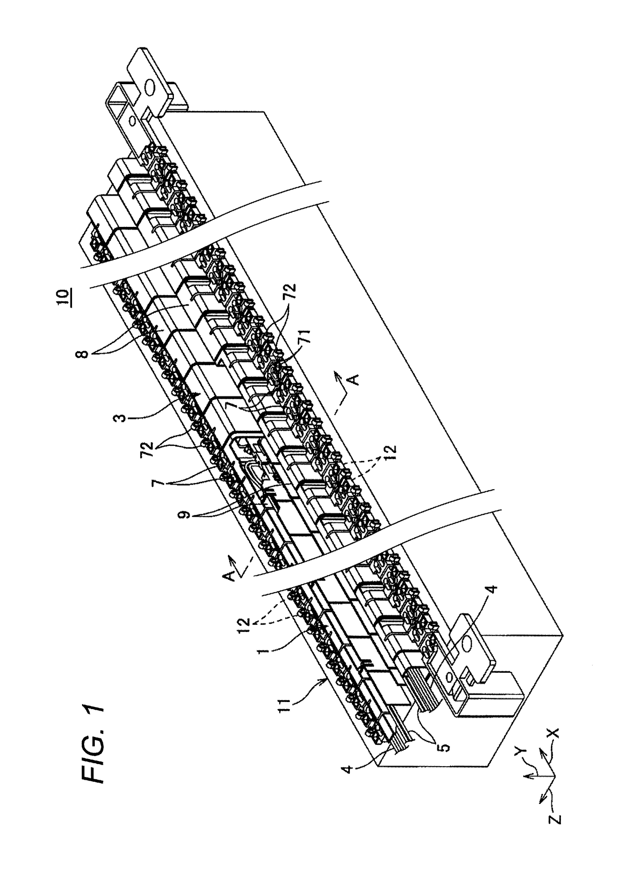
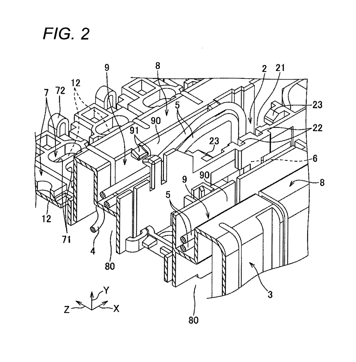
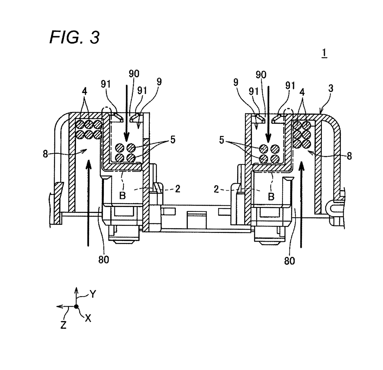
A battery connection body includes: connection conductors which electrically connect respective battery cells forming a battery assembly; a casing to which the connection conductors are mounted, and which includes a first side and a second side different from the first side; and first electric wires and second electric wires, which are wired in the casing. The casing includes: a connection conductor mounting portion; a first electric wire housing portion; and a second electric wire housing portion. The connection conductors are mounted to the connection conductor mounting portion from the first side of the casing. The first electric wires are received into the first electric wire housing portion from the first side of the casing. The second electric wires are received into the second electric wire housing portion from the second side of the casing.

Description

CROSS REFERENCE TO RELATED APPLICATION(S)[0001]This application is based on and claims priority from Japanese Patent Application (Application No. 2014-086165) filed on Apr. 18, 2014, the entire contents of which are incorporated herein by reference.BACKGROUND1. Field of the Invention[0002]One or more embodiments of the present invention relate to a battery connection body for electrically connecting battery cells forming a battery assembly, and a battery pack provided with the battery connection body.2. Description of the Related Art[0003]JP-A-2014-22256 describes a car mounted with a battery pack. The battery pack includes: a battery assembly that is an assembly of a plurality of battery cells; and a battery connection body attached to the battery assembly so as to electrically connect the battery cells with one another.[0004]For example, the battery connection body includes: a plurality of connection conductors each connecting the adjacent battery cells of the battery assembly to ...

Claims


Application Information

Patent Timeline
Patent Type & Authority Patents(United States)
IPC IPC(8): H01M2/20H01M2/10H01M50/227H01M50/271H01M50/503H01M50/51H01M50/516H01M50/522
CPCH01M2/206H01M2/1077H01M2220/20H01M50/503H01M50/516H01M50/271H01M50/51H01M50/522H01M50/227Y02E60/10H01M50/502
Inventor IKEDA, TOMOHIROKOIZUMI, KOJI
Owner YAZAKI CORP
Learn More