
Volume rendering using N-pass sampling

a volume rendering and sampling technology, applied in the field of medical imaging, can solve the problems of poor image quality, even more problematic degradation, degradation of information processing, etc., and achieve the effects of increasing the resolution of an object, increasing the rendering speed, and less density

Active Publication Date: 2012-10-23
SIEMENS MEDICAL SOLUTIONS USA INC
View PDF1 Cites 2 Cited by
  • Summary
  • Abstract
  • Description
  • Claims
  • Application Information

AI Technical Summary

Benefits of technology

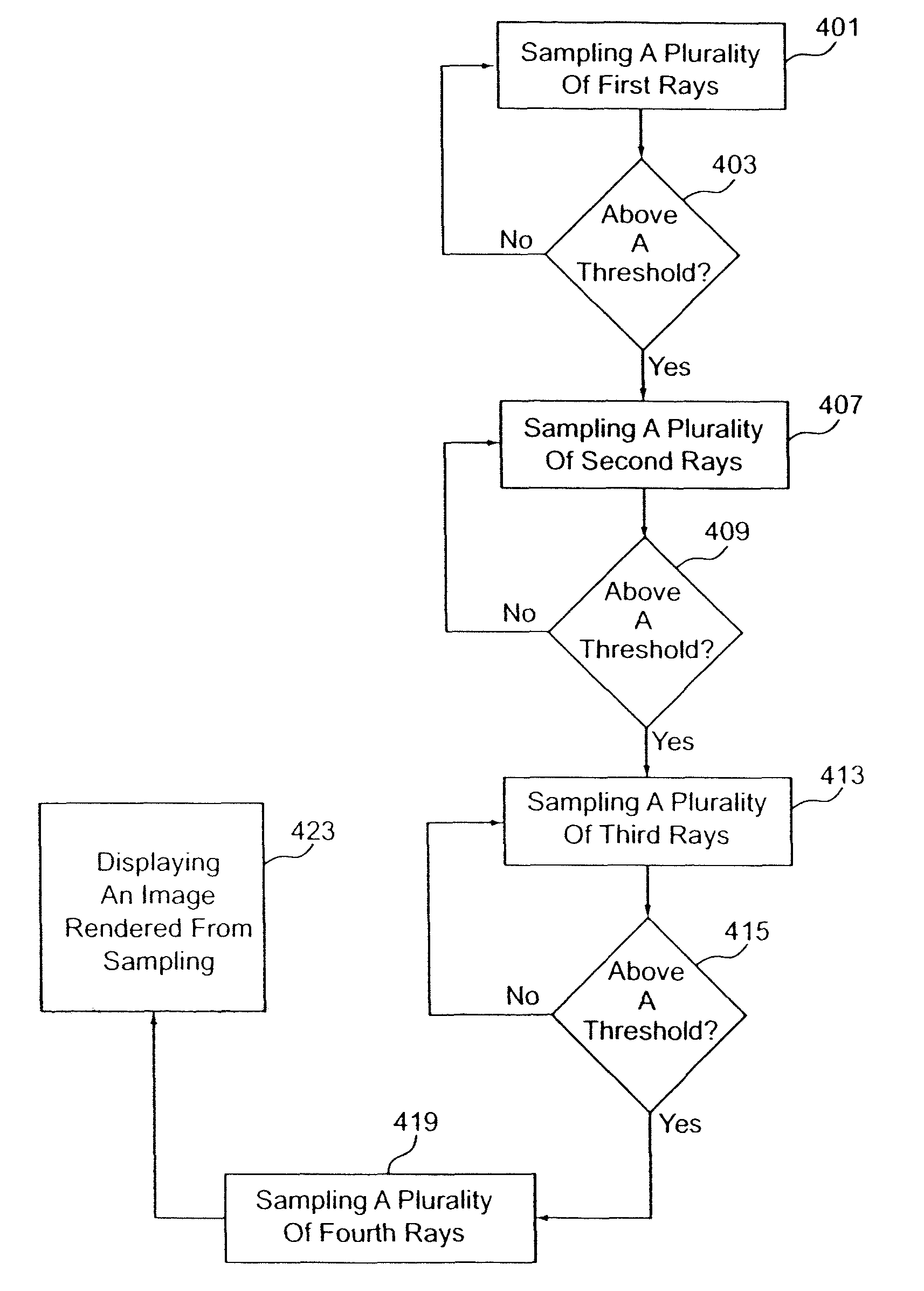
[0009]According to a third aspect, a volume rendering system for increasing resolution of an object and increasing rendering speed by rendering with a lesser density for non-object regions is provided. The system includes a memory operable to store volume data. A processor is in communication with the memory and operable to sample the volume data along a plurality of first rays in first sections, respectively. The processor is operable to sample, with a plurality of second rays having a higher spatial density than the first rays, the data in each first section having a first sample value of the respective first ray higher than a second sample value of another first ray, the difference between the first and second sample values above a first threshold. The processor is operable to compare a second sample value of at least one second ray with a third sample value of a first or second ray. The processor is operable to sample, with a plurality of third rays at different locations than the first and second rays, if the comparing to the second sample value indicates a value difference above a second threshold. A display is in communication with the processor and operable to display an image as a function of the first, second, and third rays.

Problems solved by technology

Consequently, processing of the information degrades due to intensive computation and memory access.
The degradation is even more problematic during interactive modes where the displayed image is being rotated or shifted by a medical professional for viewing.
However, reducing the image resolution in each dimension may result in poor image quality.
However, fine features, such as vessels and bronchioles, may be missed, which tends to blur the image.

Method used


Image

  • Volume rendering using N-pass sampling
  • Volume rendering using N-pass sampling
  • Volume rendering using N-pass sampling

Examples


Embodiment Construction

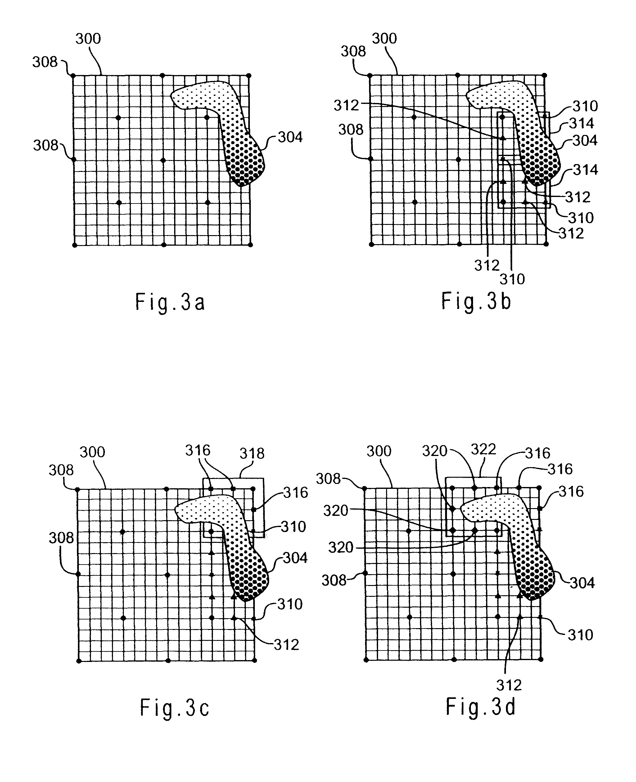
[0016]An n-pass adaptive sampling technique is used to improve image quality for volume visualization, especially for interactive mode. The technique involves sampling more rays to capture fine features of images while eliminating unnecessary rays as much as possible. Coarse features are captured in a first pass, and more sampling rays are adaptively added in image areas, such as border or edge regions, in subsequent passes. Neighboring as well as local information is utilized to achieve better rendering quality.

[0017]FIG. 1 shows one embodiment of an imaging system 100 for volume rendering using n-pass sampling. The imaging system 100 is a computed tomography (“CT”) scanner, a magnetic resonance imaging (“MRI”) system, an ultrasound system, a positron emission tomography (“PET”) scanner, or any known or future medical or non-medical imaging system. In other embodiments, the imaging system 100 is a computer, a workstation, server, and / or an image database system.

[0018]The imaging sy...


PUM


Abstract

A system and methods for volume rendering using n-pass sampling are disclosed. A plurality of first rays in a first density is sampled through a volume. Each of the first rays is in a separate section. A value of at least one first ray is compared to a first threshold. A plurality of second rays in a second density is sampled based on the comparison of the at least one first ray. The second rays are in a first section of the separate sections. The first section being for the at least one first ray. A value of at least one second ray is compared to a second threshold. A plurality of third rays is sampled in a second section spatially different than the first section based on the comparison of the at least one second ray. An image rendered from the sampling of at least the first rays is displayed.

Description

CLAIM OF PRIORITY[0001]This application claims the benefit of the U.S. provisional application 60 / 835,362 filed on Aug. 3, 2006, which is hereby incorporated by reference.FIELD OF THE INVENTION[0002]The present invention relates to medical imaging. In particular, high quality volume rendering using n-pass sampling is provided.BACKGROUND[0003]Medical professionals utilize a variety of imaging techniques to generate images of internal features of humans, animals, and other objects. For example, three dimensional (“3D”) images generated via volume rendering are useful for understanding spatial dimensions of internal features. Volume rendering may involve ray-casting in which virtual rays are cast through a volume data set, and points along the rays are sampled for image generation purposes. Ray-casting is one of the most popular rendering techniques used to generate the highest quality images. However, as volume data sets increase in size, the number of sampling rays or amount of inter...

Claims


Application Information

Patent Timeline
Patent Type & Authority Patents(United States)
IPC IPC(8): G06T15/00G06T15/50G06T15/60
CPCG06T15/08
Inventor XUE, DAQINGYANG, LINING
Owner SIEMENS MEDICAL SOLUTIONS USA INC
Learn More