
Cooling system of internal combustion engine

a technology of internal combustion engine and cooling system, which is applied in the direction of machines/engines, mechanical equipment, auxilaries, etc., can solve the problem of limiting the flexibility of arrangement of peripheral machinery included in the internal combustion engine, and achieve the effect of improving the flexibility of arrangement of peripheral machinery

Inactive Publication Date: 2012-10-23
HONDA MOTOR CO LTD
View PDF12 Cites 6 Cited by
  • Summary
  • Abstract
  • Description
  • Claims
  • Application Information

AI Technical Summary

Benefits of technology

[0004]The present invention has been made to eliminate such a disadvantage and aims to provide a cooling system of an internal combustion engine that can improve flexibility of arrangement of peripheral machinery included in the engine.
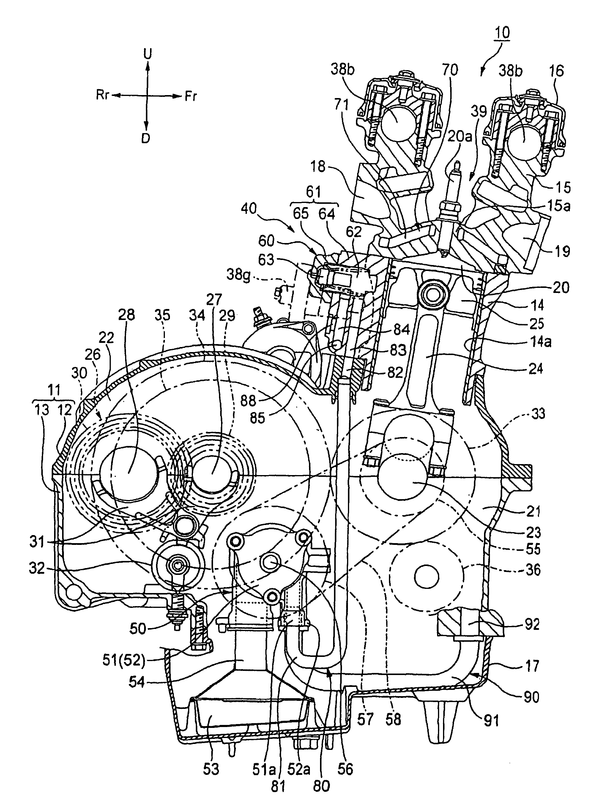
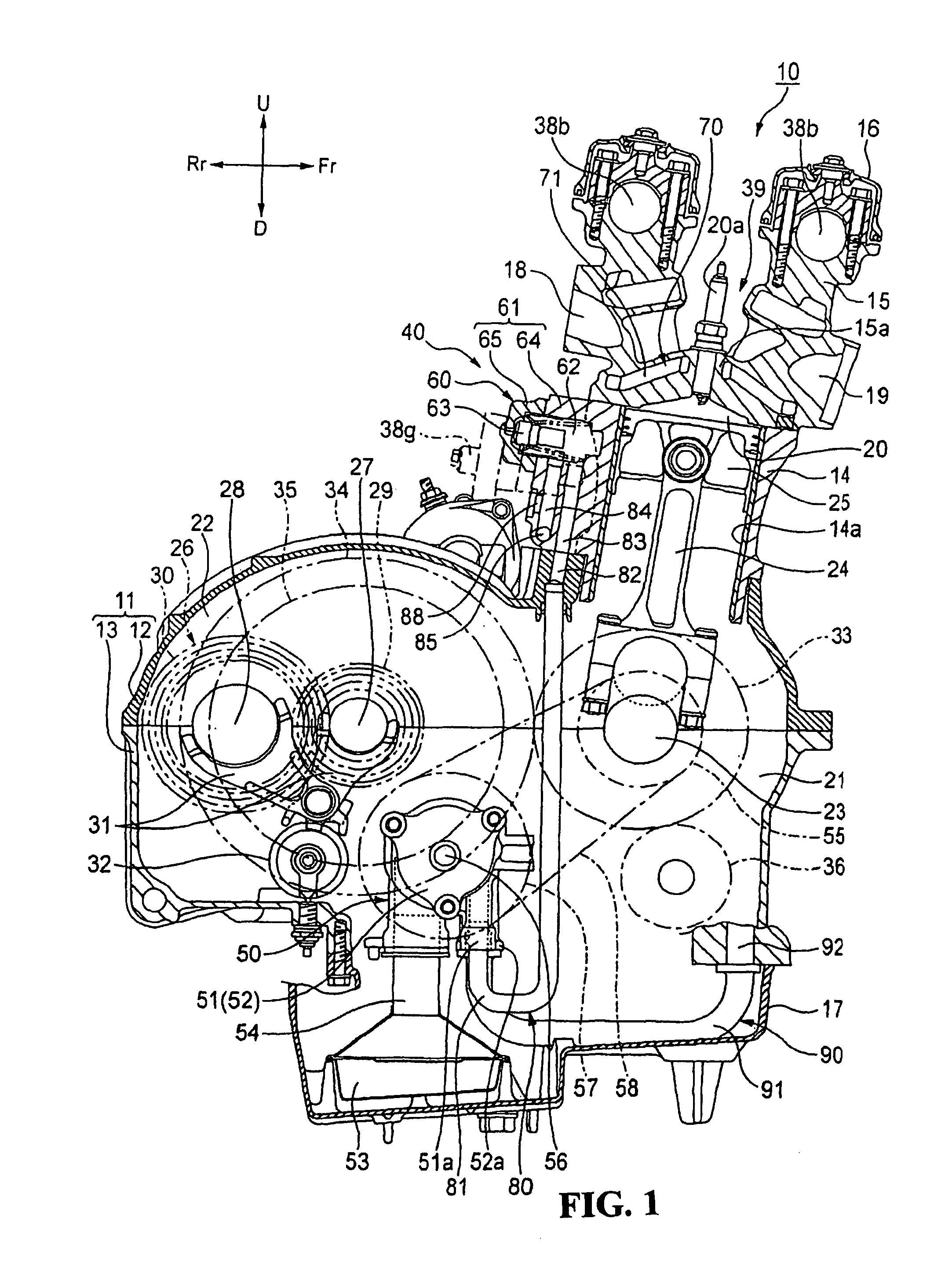
[0008]According to the cooling system of the internal combustion engine, the oil passage is formed in the rear surface portion of the cylinder block to extend along the cylinder-arrangement direction and the oil temperature sensor is attached to the oil passage in the axial direction of the oil passage. Therefore, the oil temperature sensor can be disposed as close to the cylinder block as possible. This can prevent a projecting portion from being formed on the cylinder block to improve flexibility of arrangement of peripheral machinery in the internal combustion engine. Thus, the internal combustion engine can be made compact.
[0009]According to the cooling system of the internal combustion engine, the cooling system includes the cooling portion formed in the cylinder head adapted to circulate oil to cool each cylinder; and the oil cooler adapted to supply cooled oil to the upstream side of the oil passage. Therefore, the temperature of oil immediately after cooled by the oil cooler can be detected. Thus, the oil cooled state can instantly be detected by the oil temperature sensor to thereby improve the accuracy of parameters of oil temperature used to control the internal combustion engine.
[0010]According to the cooling device of the internal combustion engine, the oil temperature sensor is disposed inwardly of the cylinder-arrangement directional end of the cylinder block. Therefore, the oil temperature sensor does not project from the cylinder-arrangement directional end of the cylinder block. Thus, it is not necessary to additionally prepare a member for protecting the oil temperature sensor. This can reduce the number of component parts to reduce the weight of the internal combustion engine.

Problems solved by technology

This limits the flexibility of arrangement of peripheral machinery included in the internal combustion engine.

Method used


Image

  • Cooling system of internal combustion engine
  • Cooling system of internal combustion engine
  • Cooling system of internal combustion engine

Examples


Embodiment Construction

[0020]An embodiment of a cooling system of an internal combustion engine according to the present invention will hereinafter be described in detail with reference to the accompanying drawings. Incidentally, the internal combustion engine of the present embodiment is mounted on a motorcycle (not shown). In the following description, the front and back or rear, the left and right, and upside and downside are based on the direction a rider faces. In the drawings, the front, back or rear, left, right, upside and downside of a motorcycle are denoted with Fr, Rr, L, R, U and D, respectively.

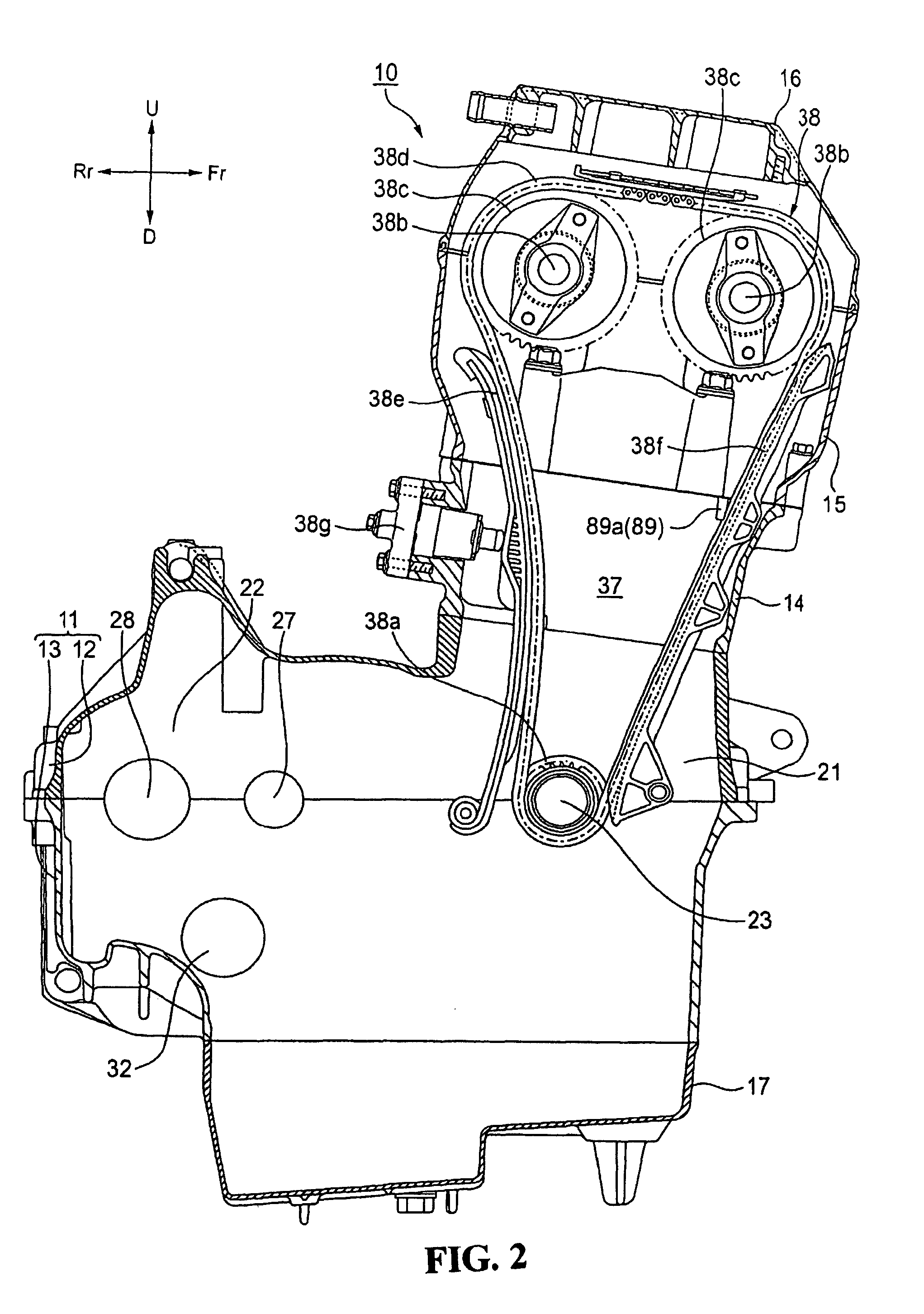
[0021]The internal combustion engine 10 of the present embodiment is, for example, an in-line four-cylinder engine as shown in FIG. 1. An outer shell of the engine mainly includes a crankcase 11 composed of an upper crankcase 12 and a lower crankcase 13; a cylinder block 14 mounted to the front upper end of the crankcase 11; a cylinder head 15 mounted to the upper end of the cylinder block 14; a cylind...


PUM


Abstract

A cooling system of an internal combustion engine is provided that can improve flexibility of arrangement of peripheral machinery included in the engine. A cooling system of an internal combustion engine includes a crankcase; a cylinder block disposed on an upper portion of the crankcase and having a plurality of cylinder bores; a cylinder head disposed on an upper portion of the cylinder block; and an oil passage formed in a rear surface portion of the cylinder block so as to extend along a cylinder-arrangement direction. The oil temperature sensor is attached to the oil passage from the axial direction of the oil passage.

Description

TECHNICAL FIELD[0001]The present invention relates generally to a cooling system of an internal combustion engine, and particularly, to a cooling system of an internal combustion engine for a motorcycle.BACKGROUND OF THE INVENTION[0002]There is known a traditional cooling system of an internal combustion engine, in which an oil temperature sensor is disposed in an oil supply passages adapted to supply oil to an oil jacket formed in a cylinder head, at a position on a rear surface of a cylinder block and above a crankcase (see e.g. Japanese Patent Laid-open No. 2006-97614).[0003]Incidentally, in the cooling system of the internal combustion engine described in Japanese Patent Laid-open No. 2006-97614 mentioned above, the oil temperature sensor is disposed perpendicularly to a cylinder-arrangement direction so that it is arranged to project from the cylinder block. This limits the flexibility of arrangement of peripheral machinery included in the internal combustion engine.SUMMARY OF ...

Claims


Application Information

Patent Timeline
Patent Type & Authority Patents(United States)
IPC IPC(8): F01M9/10
CPCF01M11/02F01P3/00F01M2011/023F01P2003/006F01P2003/024F01P2050/16
Inventor SUGIURA, HIROYUKI
Owner HONDA MOTOR CO LTD
Learn More