
Projection apparatus using variable light source

a technology of projection apparatus and light source, applied in the field of projection apparatus, can solve the problems of limitation and difficulty of high-quality image display, adverse effect of image quality, and limitation of display quality

Active Publication Date: 2012-10-09
IGNITE INC +1
View PDF26 Cites 13 Cited by
  • Summary
  • Abstract
  • Description
  • Claims
  • Application Information

AI Technical Summary

Benefits of technology

The present invention provides a technique to achieve a display gradation higher than the display gradation of a spatial light modulator in a projection apparatus comprising a spatial light modulator. This technique makes it possible to attain a display gradation precision higher than the display gradation precision of a spatial light modulator without unnecessarily complicating the control and structure of the spatial light modulator in a projection apparatus comprising the spatial light modulator. Additionally, this technique makes it possible to achieve both a more compact spatial light modulator and higher display gradation / display gradation precision in a projection apparatus.

Problems solved by technology

Even though there have been significant advances made in recent years in the technologies of implementing electromechanical micromirror devices as spatial light modulators (SLM), there are still limitations and difficulties when they are employed to display high quality images.
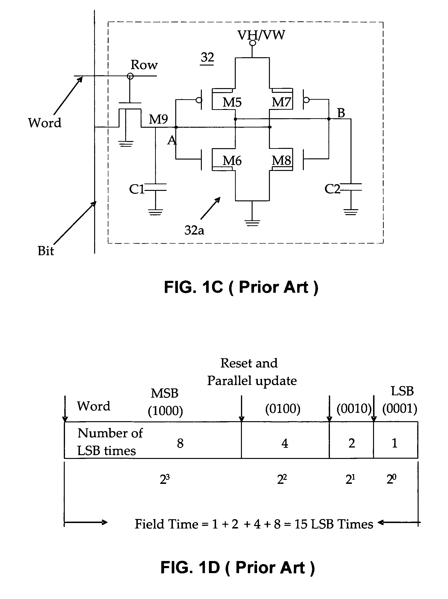
Specifically, when the display images are digitally controlled, the quality of the images is adversely affected because the images are not displayed with a sufficient number of gray scale gradations.
The on-and-off states of the micromirror control scheme as that implemented in the U.S. Pat. No. 5,214,420, and in most conventional display systems, imposes a limitation on the quality of the display.
Due to the ON-OFF states implemented in the conventional systems, there is no way of providing a shorter pulse width than the duration represented by the LSB.
The limited levels of the gray scale lead to a degradation of the display image.
Additionally, a projection apparatus as described above generally uses a light source, such as a high pressure mercury lamp or a xenon lamp, which is difficult to turn on or off at a high speed.
There is, however, already a limitation in the achievable gradation with the control of the aforementioned spatial light modulator.
Additionally, the structure and control of the spatial light modulator can become unnecessarily complicated if a high level of gradation is attempted only by controlling the spatial light modulator.
Yet the use of conventional light sources such as the above described high pressure mercury lamp or xenon lamp that has no direct control over the emission light, makes it difficult to achieve a more compact spatial light modulator due to a problem known as “etendue,” which greatly reduces the efficient usage of light.
Therefore, the application of conventional light sources to achieve an improvement in gradation while using a more compact spatial light modulator is confronted with substantial technical difficulty.

Method used


Image

  • Projection apparatus using variable light source
  • Projection apparatus using variable light source
  • Projection apparatus using variable light source

Examples


Embodiment Construction

[0061]A description of the mirror device, as the premise upon which the embodiment of the present invention is based, follows. Thereafter, a description of a preferred embodiment of the present invention is presented.

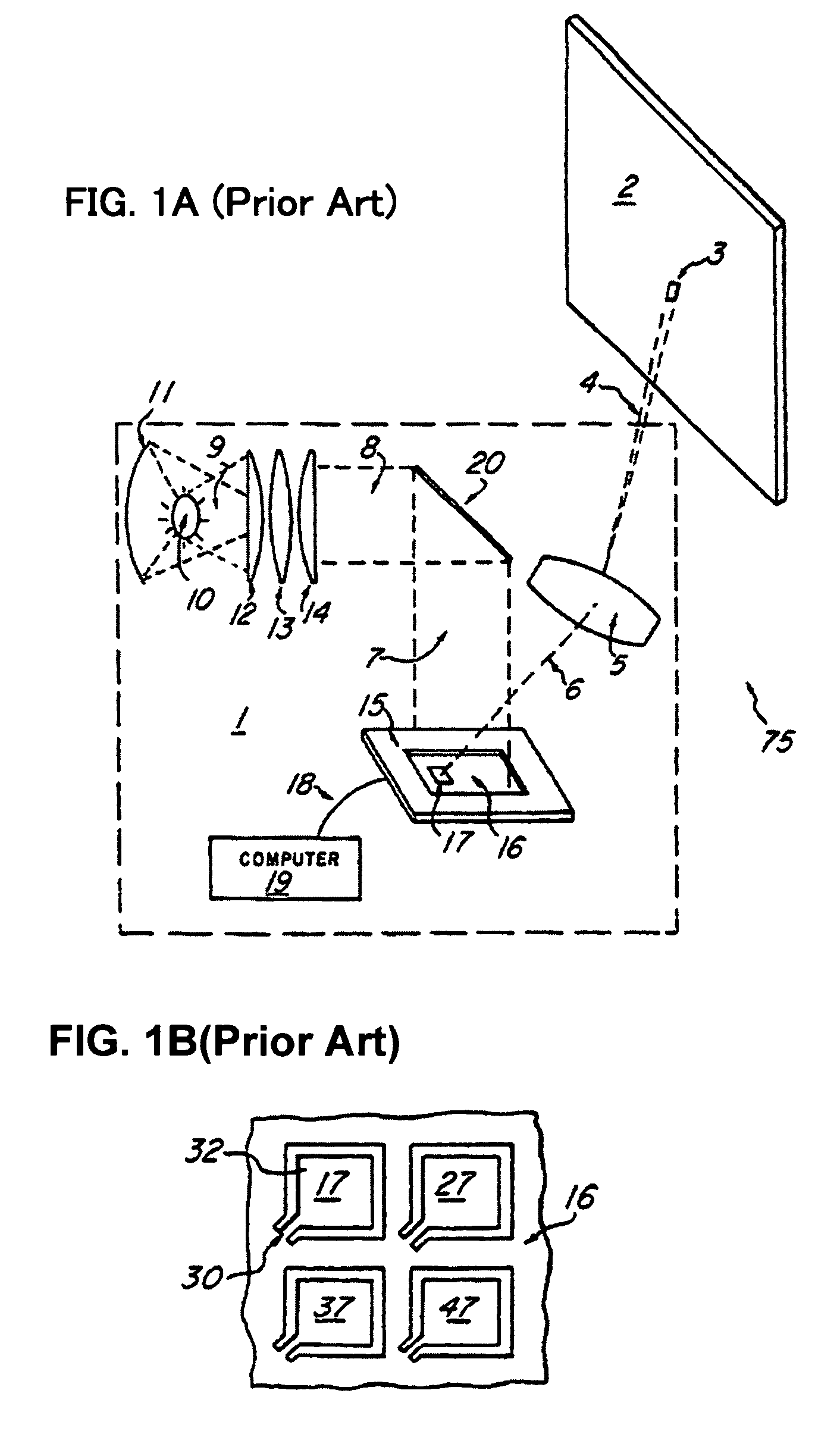
[0062]Projection apparatuses using a spatial light modulator, such as a transmissive liquid crystal, a reflective liquid crystal, a mirror array, etc., are widely known.

[0063]A spatial light modulator includes a two-dimensional array that arranges, enlarges, and then displays on a screen by way of a projection lens arrayed as tens of thousands to millions of miniature modulation elements for projecting individual pixels corresponding to an image.

[0064]The spatial light modulators generally used for projection apparatuses are of primarily two types: 1) a liquid crystal device for modulating the polarizing direction of incident light; a liquid crystal is sealed between transparent substrates and provides them with a potential, and 2) a mirror device that deflects miniatur...


PUM


Abstract

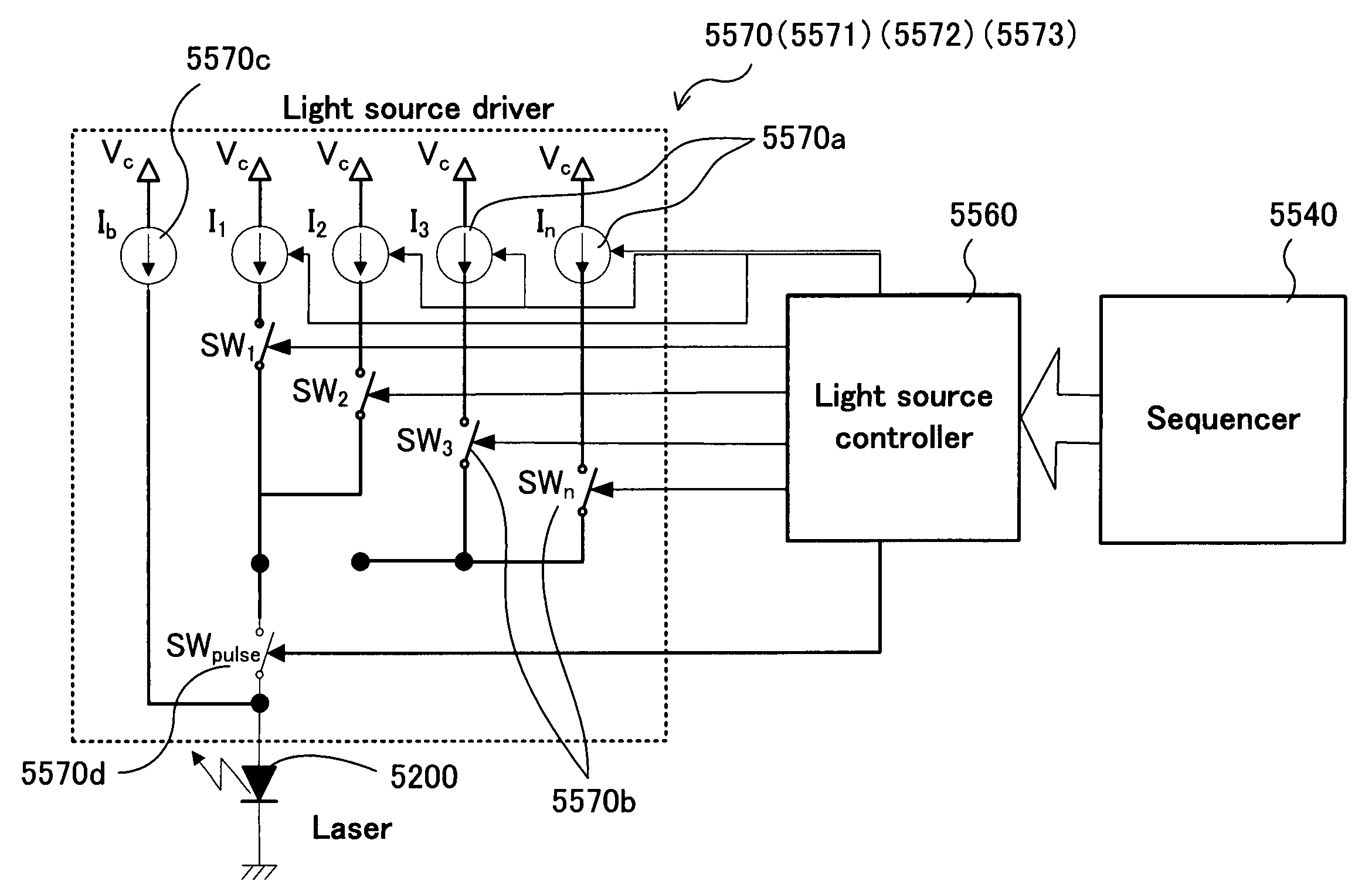
A projection apparatus using a spatial light modulator (SLM), comprising the following: at least one variable light source, at least one spatial light modulator for modulating the illumination light emitted from the variable light source in accordance with the modulation state of arrayed pixel elements, a variable light source controller for controlling modulation of the variable light source, and a spatial light modulator controller for controlling modulation of each pixel element of the spatial light modulator, wherein the variable light source controller controls the variable light source so as to reduce the period in which the modulation states of the pixel element are in transition on a display image.

Description

CROSS REFERENCE TO RELATED APPLICATIONS[0001]This is a Non-provisional application of a U.S. Patent Provisional Application No. 60 / 964,848 filed on Aug. 15, 2007. The Patent Application 60 / 964,848 is a Continuation In Part (CIP) Application of a pending U.S. patent application Ser. No. 11 / 121,543 filed on May 4, 2005 issued into U.S. Pat. No. 7,268,932. The application Ser. No. 11 / 121,543 is a Continuation In Part (CIP) Application of three previously filed Applications. These three Applications are 10 / 698,620 filed on Nov. 1, 2003, now abandoned, 10 / 699,140 filed on Nov. 1, 2003 now issued into U.S. Pat. No. 6,862,127, and 10 / 699,143 filed on Nov. 1, 2003 now issued into U.S. Pat. No. 6,903,860 by the Applicant of this Patent Applications. The disclosures made in these Patent Applications are hereby incorporated by reference in this Patent Application.BACKGROUND OF THE INVENTION[0002]1. Field of the Invention[0003]The present invention relates to a technique applicable to a project...

Claims


Application Information

Patent Timeline
Patent Type & Authority Patents(United States)
IPC IPC(8): G03B21/14
CPCG02B26/0841G09G3/3413G09G3/346H04N9/3123H04N9/3155H04N9/3197G09G3/2029G09G2310/0235G09G2310/0237G09G2310/08G09G2320/0633G09G2320/064
Inventor ARAI, KAZUMAISHII, FUSAO
Owner IGNITE INC
Learn More