
Systems and methods for side-lobe compensation in reconfigurable optical add-drop multiplexers

a technology of optical add-drop multiplexers and side-lobe compensation, which is applied in the field of optical networks, can solve the problems of system osnr penalty, system osnr penalty, system having to take even more osnr penalty due to side-lobes, etc., and achieve the effect of reducing the side-lobe of the passband

Active Publication Date: 2012-10-02
CIENA
View PDF39 Cites 9 Cited by
  • Summary
  • Abstract
  • Description
  • Claims
  • Application Information

AI Technical Summary

Benefits of technology

The solution effectively reduces passband side-lobes and maintains signal OSNR by accurately estimating ASE noise and adjusting amplifier settings, preventing unexpected signal power drops and improving network performance.

Problems solved by technology

For both constant power and constant gain amplifier control, if ASE power is not considered in the total target output power at each network node, a system will take penalty due to lower than expected channel launch power since significant ASE will share the total output power of the amplifier with the WDM signals.
However, the addition of reconfigurable optical add-drop multiplexers (ROADMs) alters this assumption.
Disadvantageously, MEMS-based WSSs have side-lobes for each channel.
Furthermore, in practice, both MEMS and LCM devices may require that a finite gap exist between adjacent pixels.
The severe under-estimating accumulated ASE power will cause unexpected signal power drop and lead to OSNR penalty in the system.
The OSNR penalty introduced by WSS side-lobes is mainly caused by launching lower than expected signal power into the system along the amplifier chain, due to larger than expected ASE and under-estimated amplifier target power, i.e. side-lobes utilize amplifier power designated for the signal bandwidth.
Alternatively, if the WSSs are working at the worst-case condition in their specification, the system has to take even more OSNR penalty due to the side-lobes.
Accordingly, side-lobes due to WSS ROADMs significantly impair network performance, and current systems and methods are inadequate for compensation.

Method used


Image

  • Systems and methods for side-lobe compensation in reconfigurable optical add-drop multiplexers
  • Systems and methods for side-lobe compensation in reconfigurable optical add-drop multiplexers
  • Systems and methods for side-lobe compensation in reconfigurable optical add-drop multiplexers

Examples


Embodiment Construction

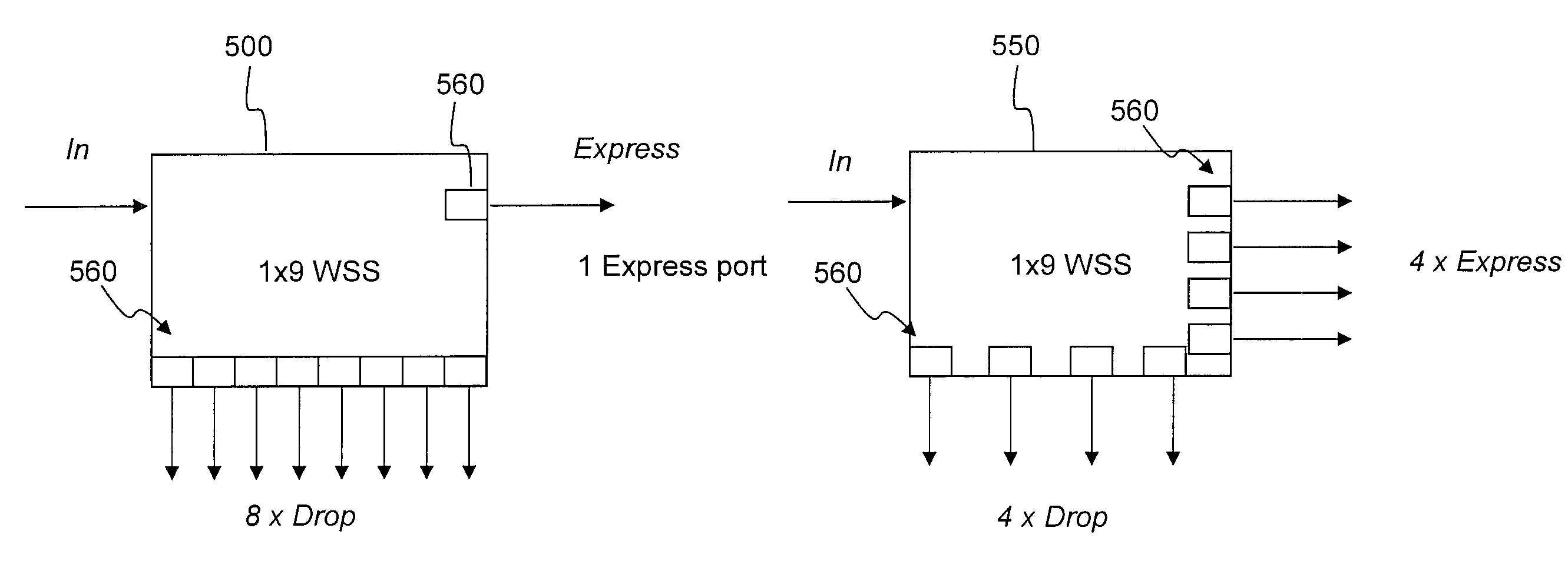
[0034]In various exemplary embodiments, the present invention provides systems and methods to reduce passband side-lobes associated with WSS-based ROADMs by applying a filter on each channel. In an exemplary embodiment, a comb filter, such as a thin film filter or an interleaver, is utilized. Additionally, the present invention provides systems and methods to adaptively control amplifier target power and per wavelength target power to maintain signal launching power as per design in networks with WSS-based ROADMs. Accordingly, signal OSNR does not collapse faster than other similar configured system without WSS-based ROADM. In order to correct amplifier target power, the present invention utilizes system information about side-lobe size and OSNR at each amplifier. Related information, such as ASE level and size of side-lobes at each channel from upstream amplifiers, is passed to a network controller at each amplifier. Meanwhile, with target signal level and local WSS attenuation set...


PUM


Abstract

Systems and methods to reduce passband side-lobes associated with WSS-based ROADMs by applying a filter on each channel are provided. In an exemplary embodiment, a comb filter, such as a thin film filter or an interleaver, is utilized. Additionally, the present invention provides systems and methods to adaptively control amplifier target power and per wavelength target power to maintain signal launching power as per design in networks with WSS-based ROADMs. Accordingly, signal OSNR does not collapse faster than other similar configured system without WSS-based ROADM. In order to correct amplifier target power, the present invention utilizes system information about side-lobe size and OSNR at each amplifier.

Description

CROSS-REFERENCE TO RELATED APPLICATION(S)[0001]This application is a continuation-in-part of co-pending U.S. patent application Ser. No. 11 / 726,934 filed Mar. 23, 2007, and entitled “SYSTEMS AND METHODS FOR ADAPTIVE GAIN CONTROL TO COMPENSATE OSNR PENALTY CAUSED BY SIDE-LOBE OF MEMS-BASED RECONFIGURABLE OPTICAL ADD-DROP MULTIPLEXERS,” the contents of which are incorporated in full by reference herein.FIELD OF THE INVENTION[0002]The present invention relates generally to optical networks. More specifically, the present invention relates to systems and methods for comb filters to compensate for an optical signal-to-noise ratio (OSNR) penalty caused by the side-lobes created by wavelength selective switch (WSS)-based reconfigurable optical add-drop multiplexers (ROADMs) using micro-electromechanical systems (MEMS) or liquid-crystal modulators (LCM).BACKGROUND OF THE INVENTION[0003]Amplified spontaneous emission (ASE) noise is one of the main noise sources in optical amplifiers. ASE is ...

Claims


Application Information

Patent Timeline
Patent Type & Authority Patents(United States)
IPC IPC(8): G02B6/28H04J14/00
CPCH04J14/0206H04J14/0209H04J14/0212H04J14/0217H04J14/0221H04J14/02216
Inventor YANG, XIAOHUIZHU, ZHONGHUA
Owner CIENA
Learn More