
Dynamic cell bonding (DCB) for radio-over-fiber (RoF)-based networks and communication systems and related methods

a radio-over-fiber (rof) network and communication system technology, applied in multiplex communication, transmission monitoring, instruments, etc., can solve the problems of varying loss response, fading nature of signal propagation, and impede wireless data transmission

Active Publication Date: 2012-09-25
CORNING OPTICAL COMM LLC
View PDF430 Cites 58 Cited by
  • Summary
  • Abstract
  • Description
  • Claims
  • Application Information

AI Technical Summary

Benefits of technology

The patent text discusses the use of dynamic cell bonding (DCB) to compensate for the limitations of multi-mode optical fiber (MMF) in wireless communication systems. The text explains that picocells, which are small RF coverage areas, can be created by using wireless access points connected to a head-end controller or unit. However, the bandwidth limitations of the MMF can affect the SNR (signal-to-noise ratio) of wireless data transmission. The text proposes the use of signal processing techniques, such as MIMO and beam forming, to improve the SNR. The text also highlights the problem of varying bandwidth responses among optical fibers and proposes a solution to mitigate the impact of these variations on wireless communication systems. Overall, the patent text aims to improve the stability and reliability of wireless communication systems using DCB and signal processing techniques.

Problems solved by technology

One problem that can exist with wireless communication systems is the multi-path (fading) nature of signal propagation.
In addition to the factors affecting SNR, variation in bandwidth response distribution among optical fiber links can also impede wireless data transmission.
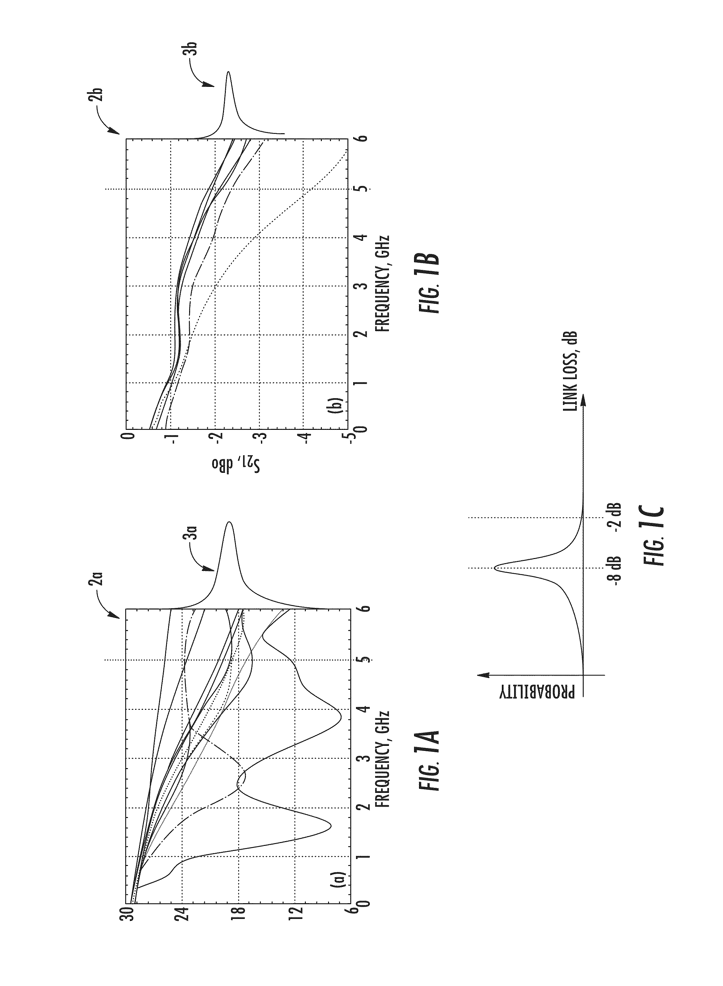
For example, multi-mode optical fibers (MMF) used in providing communications links can have varying distributions of bandwidth responses thus causing varying loss responses.
This variability results in the unpredictable behavior and operation of such wireless systems.
However, the fifty (50) μm core MMFs provided in the example of FIG. 1B may be more expensive than the 62.5 μm core MMFs provided in the example of FIG. 1A.
MMFs having larger variations in bandwidth distribution may be less expensive to employ in wireless communication systems, but may result in unpredictable behavior having a deleterious effect on the operation of optical fiber enabled wireless communication systems.

Method used


Image

  • Dynamic cell bonding (DCB) for radio-over-fiber (RoF)-based networks and communication systems and related methods
  • Dynamic cell bonding (DCB) for radio-over-fiber (RoF)-based networks and communication systems and related methods
  • Dynamic cell bonding (DCB) for radio-over-fiber (RoF)-based networks and communication systems and related methods

Examples


Embodiment Construction

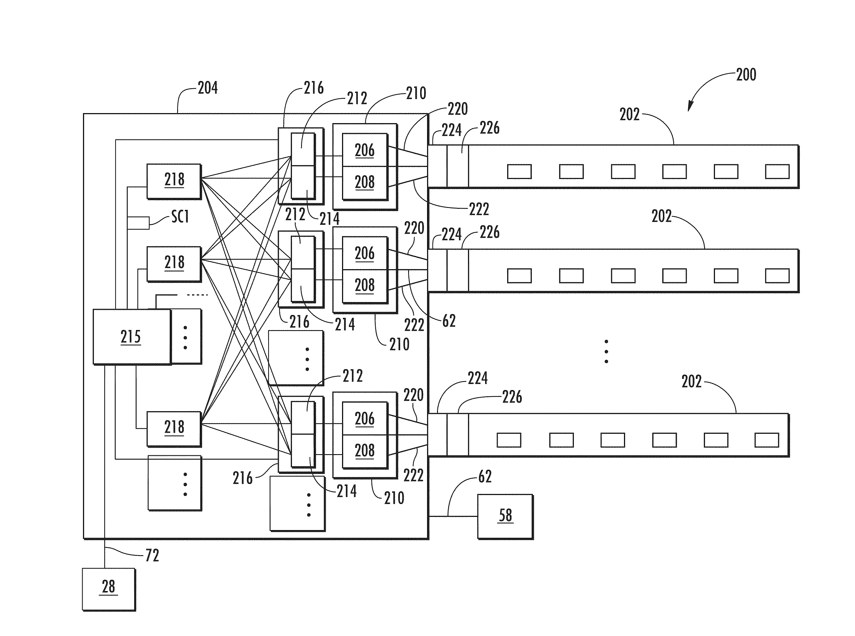
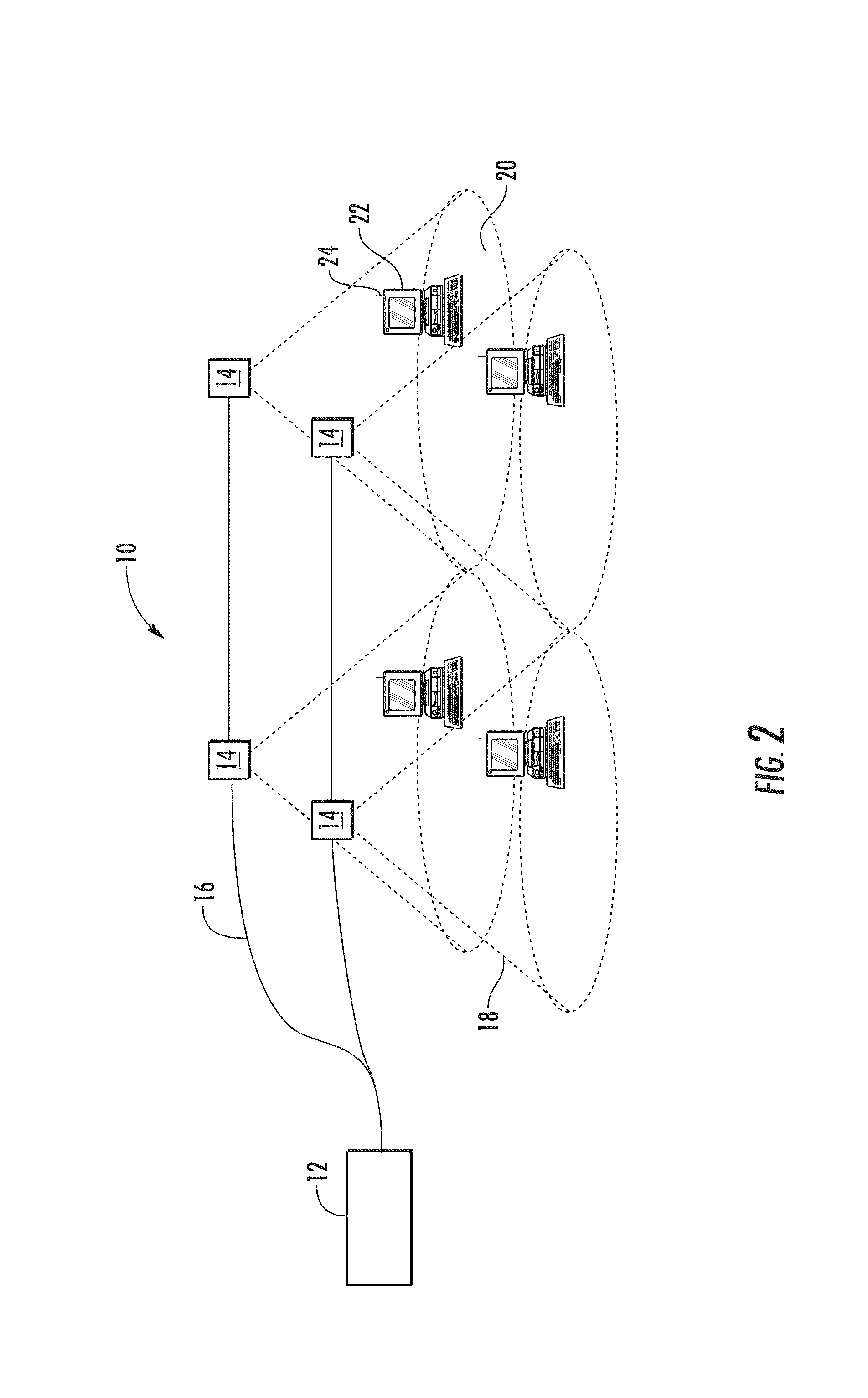
[0012]Embodiments disclosed in the detailed description include communication devices, systems, and methods for dynamic cell bonding (DCB) for Radio-over-Fiber (RoF)-based networks and communication systems. In one embodiment, a method of operating an optical fiber-based wireless communication system is provided. The method comprises determining a first plurality of remote units in a cloud bonded to a communication session, measuring a received signal strength and / or a data rate from each of the first plurality of remote units, measuring a received signal strength and / or an estimated data rate from each of a second plurality of remote units in the cloud not bonded to the communication session, and dynamically bonding one of the second plurality of remote units to the communication session if the measured received signal strength or the estimated data rate of the one of the second plurality of remote units is greater than the measured received signal strength or the data rate of one ...


PUM


Abstract

Communication devices, systems, and methods for dynamic cell bonding (DCB) for Radio-over-Fiber (RoF)-based networks and communication systems are disclosed. In one embodiment, a method of operating an optical fiber-based wireless communication system is provided. The method includes determining a first plurality of remote units in a cloud bonded to a Radio-over-Fiber (RoF) communication session. The method also includes measuring a received signal strength from each of the first plurality of remote units. The method also includes measuring a received signal strength from each of a second plurality of remote units in the cloud not bonded to the RoF communication session. At least one of the second plurality of remote units is dynamically bonded to the RoF communication session if the measured received signal strength of the one of the second plurality of remote units is greater than the measured received signal strength of the first plurality of remote units.

Description

BACKGROUND[0001]1. Field of the Disclosure[0002]The technology of the disclosure relates to dynamic cell bonding (DCB) and, more specifically, to the use of DCB to compensate for the bandwidth limitations of multi-mode optical fiber (MMF).[0003]2. Technical Background[0004]Wireless communication is rapidly growing, with ever-increasing demands for high-speed mobile data communication. As an example, so-called “wireless fidelity” or “WiFi” systems and wireless local area networks (WLANs) are being deployed in many different types of areas (coffee shops, airports, libraries, etc.). Wireless communication systems communicate with wireless devices called “clients,” which must reside within the wireless range or “cell coverage area” in order to communicate with the access point device.[0005]One approach to deploying a wireless communication system involves the use of “picocells.” Picocells are radio frequency (RF) coverage areas having a radius in the range from about a few meters up to ...

Claims


Application Information

Patent Timeline
Patent Type & Authority Patents(United States)
IPC IPC(8): H04B10/08
CPCH04B10/25753H04B10/2581H04B7/0413H04W48/20
Inventor KOBYAKOV, ANDREYSAUER, MICHAEL
Owner CORNING OPTICAL COMM LLC
Learn More