
Delay distributed virtually-concatenated data traffic

a technology of virtual concatenation and delay, applied in the field of data communication networks, can solve the problems of insufficient bandwidth efficiency and underutilization of fixed-bandwidth connections of conventional circuit-switched networks, and achieve the effects of reducing the buffer requirement at the destination node, supporting more traffic in the network, and reducing the buffer requirement on the nod

Active Publication Date: 2012-09-18
WSOU INVESTMENTS LLC
View PDF10 Cites 0 Cited by
  • Summary
  • Abstract
  • Description
  • Claims
  • Application Information

AI Technical Summary

Benefits of technology

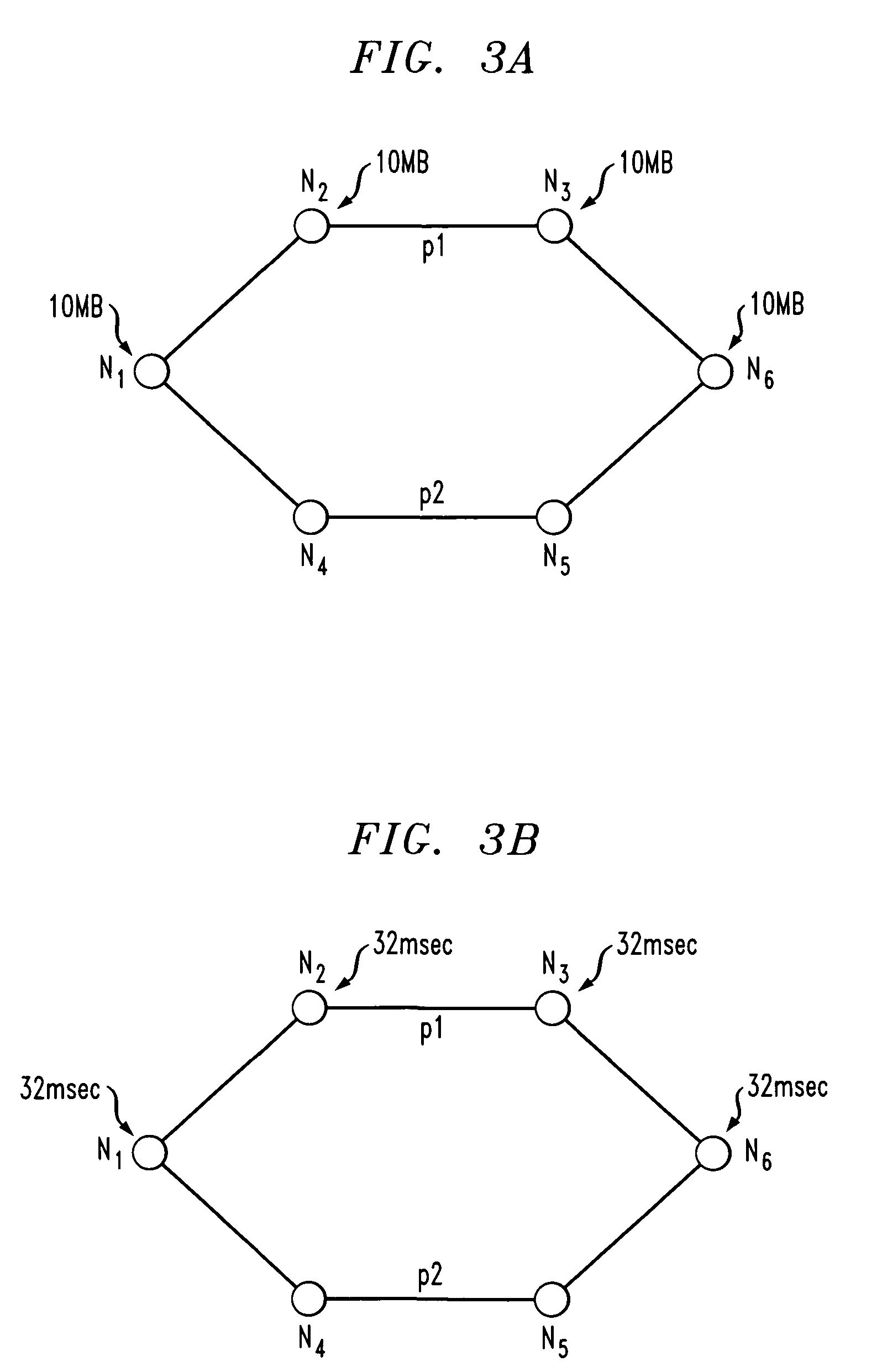
"The present invention provides network design techniques and techniques for routing virtually-concatenated data traffic in a network in a manner which distributes delay to intermediate nodes of the network. These techniques involve determining multiple paths to route the traffic demand from a source node to a destination node in the network. The paths are selected in a way that the delay is distributed over the paths, reducing delay at the destination node and minimizing the buffer size required. The techniques also allow for the recombination of members of a virtually-concatenated group at the destination node. Overall, these techniques improve network performance by reducing buffer requirements and allowing for more traffic."

Problems solved by technology

Although such networks are advantageous in that they incorporate substantial reliability and protection mechanisms, their primary disadvantage has been a lack of bandwidth efficiency.
Since data traffic is inherently bursty, it leads to underutilization of the fixed-bandwidth connections of conventional circuit-switched networks.
However, this requires the availability of large memory buffers at the destination nodes to reassemble the original traffic and can become a bottleneck in supporting traffic.

Method used


Image

  • Delay distributed virtually-concatenated data traffic
  • Delay distributed virtually-concatenated data traffic
  • Delay distributed virtually-concatenated data traffic

Examples


Embodiment Construction

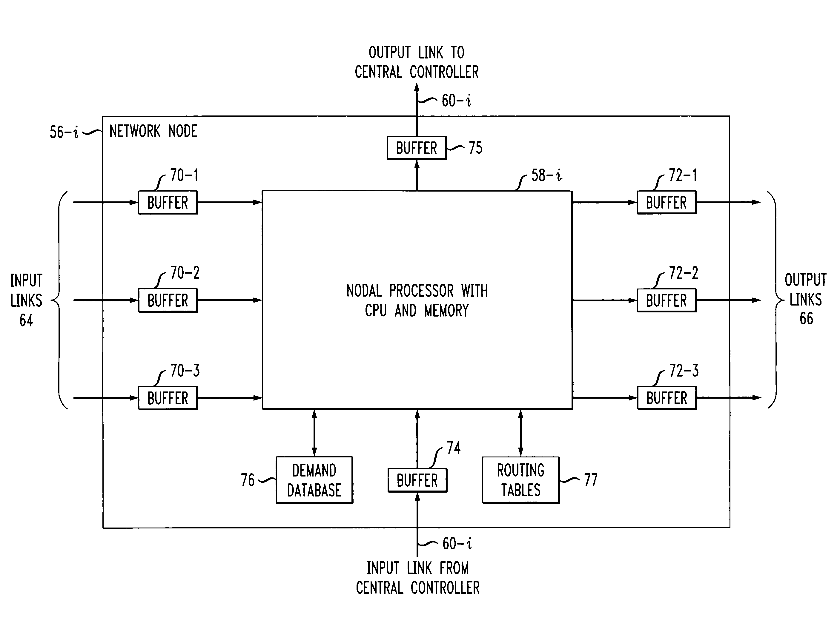
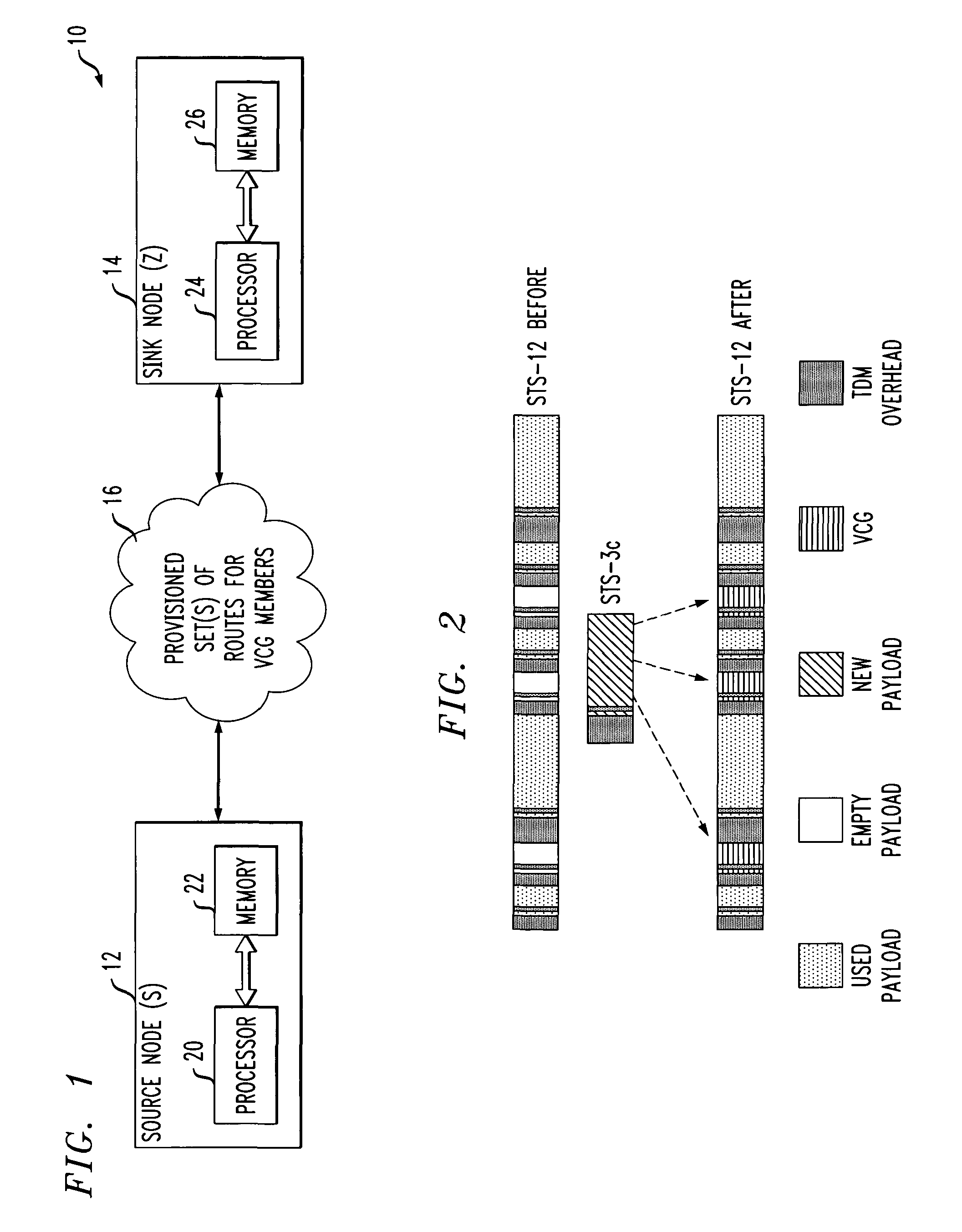
[0026]The invention will be illustrated herein in conjunction with illustrative embodiments of routing and design algorithms, as well as a network-based system and example network nodes in which the algorithms may be implemented. It should be understood, however, that the invention is not limited to use with the particular routing or design algorithms, network-based system or network node implementations described, but is instead more generally applicable to any routing or design application, network-based system or node implementation in which it is desirable to distribute delay associated with virtually-concatenated data traffic over intermediate nodes of the network rather than just at a destination node.

[0027]As used herein, an “intermediate node” generally refers to a node in a path other than the destination node. This may include the source node and nodes between the source node and the destination node. However, it is to be understood that any given node may function as one ...


PUM


Abstract

Network design techniques and techniques for routing virtually-concatenated data traffic in a network in a manner which distributes delay to intermediate nodes of the network are disclosed. For example, in one aspect of the invention, a technique for routing virtually-concatenated data traffic in a network comprising a plurality of nodes comprises, for a given traffic demand to be routed from a source node to a destination node in the network, the following steps / operations. Two or more paths are determined to route the given traffic demand. Each of the two or more paths correspond to a member of a virtually-concatenated group. At least one path of the two or more paths comprises the source node, the destination node and at least one other node coupled between the source node and the destination node. Further, at least a subset of the source node, the destination node and the one other node buffer at least a portion of the given traffic demand such that a delay is distributed over the at least one path. The given traffic demand is routed over the two or more determined paths. The at least one path is preferably the shorter of the two or more determined paths.

Description

RELATED APPLICATIONS[0001]The present invention is related to the inventions described in U.S. patent application Ser. No. 10 / 446,220, filed May 28, 2003 and entitled “Fast Restoration for Virtually-Concatenated Data Traffic,” U.S. patent application Ser. No. 10 / 745,881 filed Dec. 26, 2003 and entitled “Route Determination Method and Apparatus for Virtually-Concatenated Data Traffic,” U.S. patent application Ser. No. 10 / 856,444, filed May 28, 2004 and entitled “Route Determination with Differential Delay Compensation For Virtually-concatenated Data Traffic,” and U.S. patent application Ser. No. 10 / 949,638, filed Sep. 24, 2004 and entitled “Differential Delay Constrained Routing For Virtually-concatenated Data Traffic”, the disclosures of which are incorporated by reference herein.FIELD OF THE INVENTION[0002]The present invention relates generally to data communication networks which utilize virtual concatenation. More particularly, the invention relates to techniques for routing vir...

Claims


Application Information

Patent Timeline
Patent Type & Authority Patents(United States)
IPC IPC(8): G01R11/00
CPCH04L45/00
Inventor ALICHERRY, MANSOOR ALI KHANNAGESH, HARSHA S.PHADKE, CHITRA A.POOSALA, VISWANATH
Owner WSOU INVESTMENTS LLC
Learn More