
Multi-stage decoder for error-correcting codes

a multi-stage decoder and error-correcting technology, applied in the field of decoding codewords, can solve the problems of maximum likelihood decoders that cannot be constructed for special classes of error-correcting codes, the difficulty of decoding corrupted messages, and the decoding method of error-correcting, etc., to speed up the decoding of ldpc codes, improve the wer of multi-stage decoders, and shorten the average decoding time

Active Publication Date: 2012-09-04
MITSUBISHI ELECTRIC RES LAB INC
View PDF9 Cites 15 Cited by
  • Summary
  • Abstract
  • Description
  • Claims
  • Application Information

AI Technical Summary

Benefits of technology

The invention is a multi-stage decoder that combines multiple sub-decoders to improve the performance of decoding. The sub-decoders are ranked based on their word error rate and processing time. The first sub-decoder has the highest error rate and the last sub-decoder has the highest processing time. The sub-decoders are activated only when the preceding sub-decoder fails to converge to a valid codeword. The faster sub-decoders correct most errors, resulting in a shorter average decoding time. The multi-stage decoder improves the WER and speeds up the decoding of LDPC codes. It also reduces the complexity of optimal ML decoding performance in the high SNR regime. The invention also improves upon QBP decoders by only updating a small fraction of messages from variable and check nodes, reducing the decoding requirements.

Problems solved by technology

A fundamental problem in the field of data storage and communication is the development of practical decoding methods for error-correcting codes (ECC).
However, as the size of the parameters N and k increases, so does the difficulty of decoding corrupted messages.
In practice, maximum likelihood decoders can only be constructed for special classes of error-correcting codes.
On the other hand, as the number of possible messages increases, the cost and complexity of implementing the quantized BP decoder tends to increase as well.
Unfortunately, LP decoding is more complex than BP decoding.
Often, there is a trade-off between the WER performance of a decoder and the time it takes the decoder to process a block.
Simple decoders tend to have a small processing time but poor WER performance while more complex decoders tend to have a longer processing time and better WER performance.

Method used


Image

  • Multi-stage decoder for error-correcting codes
  • Multi-stage decoder for error-correcting codes
  • Multi-stage decoder for error-correcting codes

Examples


Embodiment Construction

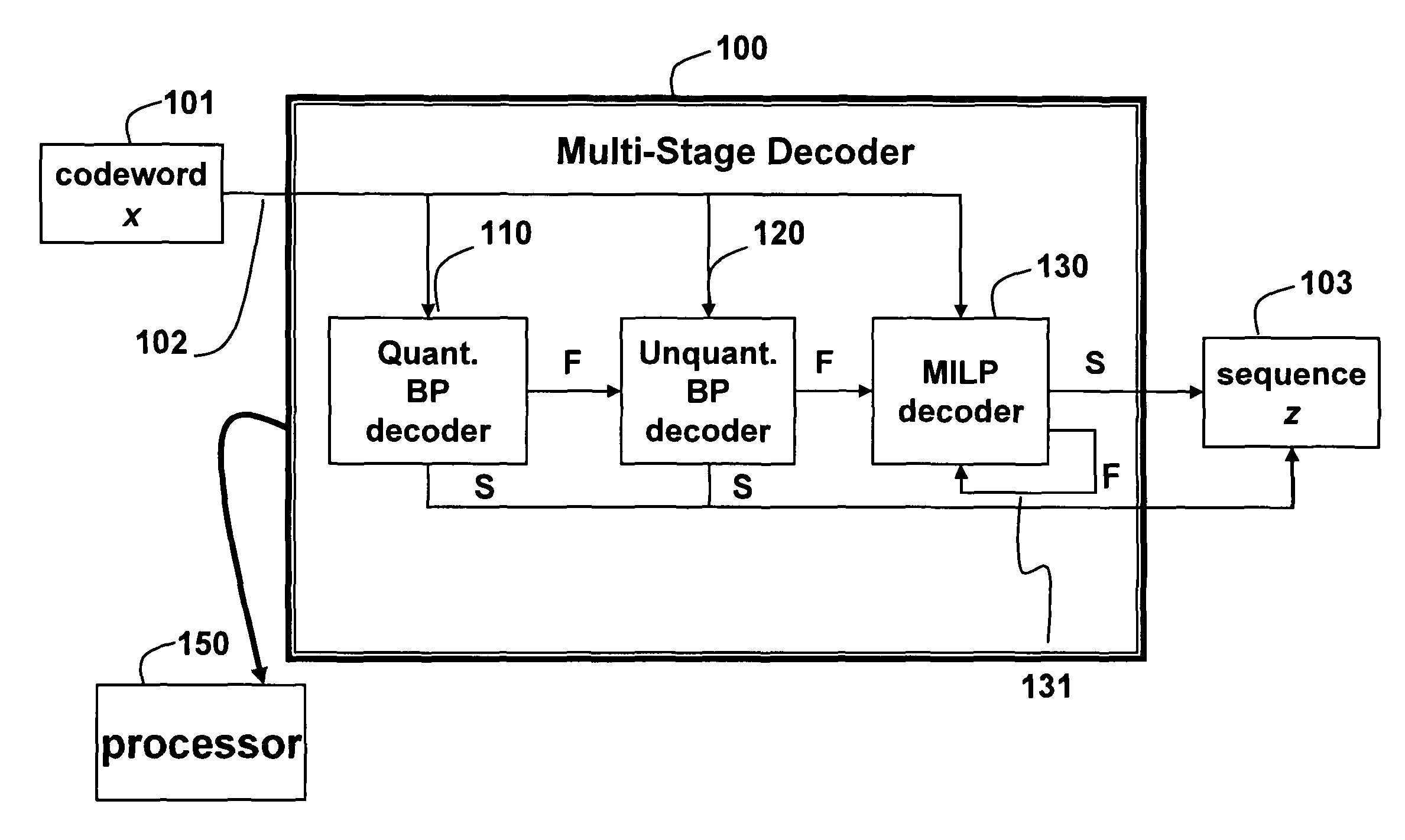
[0081]FIG. 1 shows a multi-stage decoder 100 for low-density parity-check (LDPC) codes according to embodiments of our invention. The decoder includes a quantized belief propagation (QBP) sub-decoder 110, an unquantized BP (UBP) sub-decoder 120, and a linear programming (LP) decoder or mixed-integer linear programming (MILP) sub-decoder 130, connected sequentially.

[0082]The multi-stage decoder 100 receives a codeword x 101 transmitted via a noisy channel 102. The sub-decoder 110 attempts to decode the codeword 101. If the sub-decoder 110 fails, then the sub-decoder 120 attempts to decode. If the sub-decoder 120 fails, then the sub-decoder 130 attempts to decode, until a termination condition in reached. The sub-decoders are arranged so that a next sub-decoder in the sequence has a slower processing time (T) and better word error rate (WER), than a previous sub-decoder, i.e., TQBPUBPMILP, and WERQBP>>WERUBP>>WERMILP.

[0083]A “decoding failure” indicates that the specified decoder fail...


PUM


Abstract

A multi-stage decoder decodes a block of symbols, received via a noisy channel, to a codeword. The decoder includes multiple sub-decoders connected sequentially, and wherein a next sub-decoder has a slower processing time and better word error rate than a previous sub-decoder, and wherein the next sub-decoder is only executed if the previous decoder fails to decode the block sequence of symbols, and a last sub-decoder is executed until a termination condition is reached.

Description

RELATED APPLICATION[0001]This U.S. patent application is a Continuation-in-Part of U.S. patent application Ser. No. 11 / 764,938, “Maximum Likelihood Decoding via Mixed-Integer Adaptive Linear Programming,” filed by Draper et al., on Jun. 19, 2007, now U.S. Pat. No. 7,945,845, incorporated herein by reference. This application is also related to Ser. No. 12 / 360,839 co-filed herewith.FIELD OF THE INVENTION[0002]This invention relates generally to decoding codewords of an error-correcting code, and more particularly to decoding codewords using a multi-stage decoder.BACKGROUND OF THE INVENTION[0003]Error-Correcting Codes[0004]A fundamental problem in the field of data storage and communication is the development of practical decoding methods for error-correcting codes (ECC).[0005]One very important class of error-correcting codes is the class of linear block error-correcting codes. Unless specified otherwise, any reference to a “code” herein refers to a linear block error-correcting code...

Claims


Application Information

Patent Timeline
Patent Type & Authority Patents(United States)
IPC IPC(8): H03M13/03
CPCH03M13/1108H03M13/1111H03M13/112H03M13/1194H03M13/2957H03M13/3707H03M13/3761H03M13/45H03M13/6577H03M13/658H04L1/005H04L1/0053
Inventor YEDIDIA, JONATHAN S.WANG, YIGEDRAPER, STARK C.
Owner MITSUBISHI ELECTRIC RES LAB INC
Learn More