
Road vehicle driver behaviour analysis method

a technology for driving behaviour and road vehicles, applied in the direction of driving input parameters, driving parameters, external condition input parameters, etc., can solve the problems of limited effectiveness and scope, driver distraction, indecision, high speed,

Active Publication Date: 2012-09-04
T E -SYST & ADVANCED TECH ENG
View PDF3 Cites 14 Cited by
  • Summary
  • Abstract
  • Description
  • Claims
  • Application Information

AI Technical Summary

Benefits of technology

"The present invention provides a method for analyzing the behavior of drivers in road vehicles that is cost-effective and easy to implement. The method aims to overcome the limitations of existing methods and provide a more accurate analysis of driver behavior."

Problems solved by technology

Driver distraction, indecision, and high speed are the major causes of road vehicle accidents.
The symptoms of anomalous driving behaviour are related to the commands imparted by the driver to the vehicle, and to the kinematic response of the vehicle to them (e.g. anomalous speed and / or acceleration), but this information can very easily be confused with anomalous traffic situations, and as such is of limited effectiveness and scope.
A georeference map, however, poses several problems by having to be constantly updated, and by inevitably involving errors which may even seriously affect driver behaviour analysis.
More specifically, the method is based on algorithms which classify dangerous driving situations, such as a sharp bend, sudden acceleration / deceleration, erratic steering, etc., but fails to identify dangerous situations not taken into account at the algorithm learning stage.
Moreover, this method, too, is not fully dependable in all driving situations, and may therefore mistake normal for dangerous behaviour, and vice versa.
What the state of the art does not take sufficiently into account is the extent to which anomalous-driving indicators depend on the motoring context.
That is, no known method provides for a georeference (i.e. spatial location) of the dynamic vehicle signals or driver control signals used to determine driver behaviour.

Method used


Image

  • Road vehicle driver behaviour analysis method
  • Road vehicle driver behaviour analysis method
  • Road vehicle driver behaviour analysis method

Examples


Embodiment Construction

[0008]It is an object of the present invention to provide a road vehicle driver behaviour analysis method designed to eliminate the above drawbacks, and which at the same time is cheap and easy to implement.

[0009]According to the present invention, there is provided a road vehicle driver behaviour analysis method as claimed in the attached Claims.

BRIEF DESCRIPTION OF THE DRAWINGS

[0010]A non-limiting embodiment of the present invention will be described by way of example with reference to the accompanying drawings, in which:

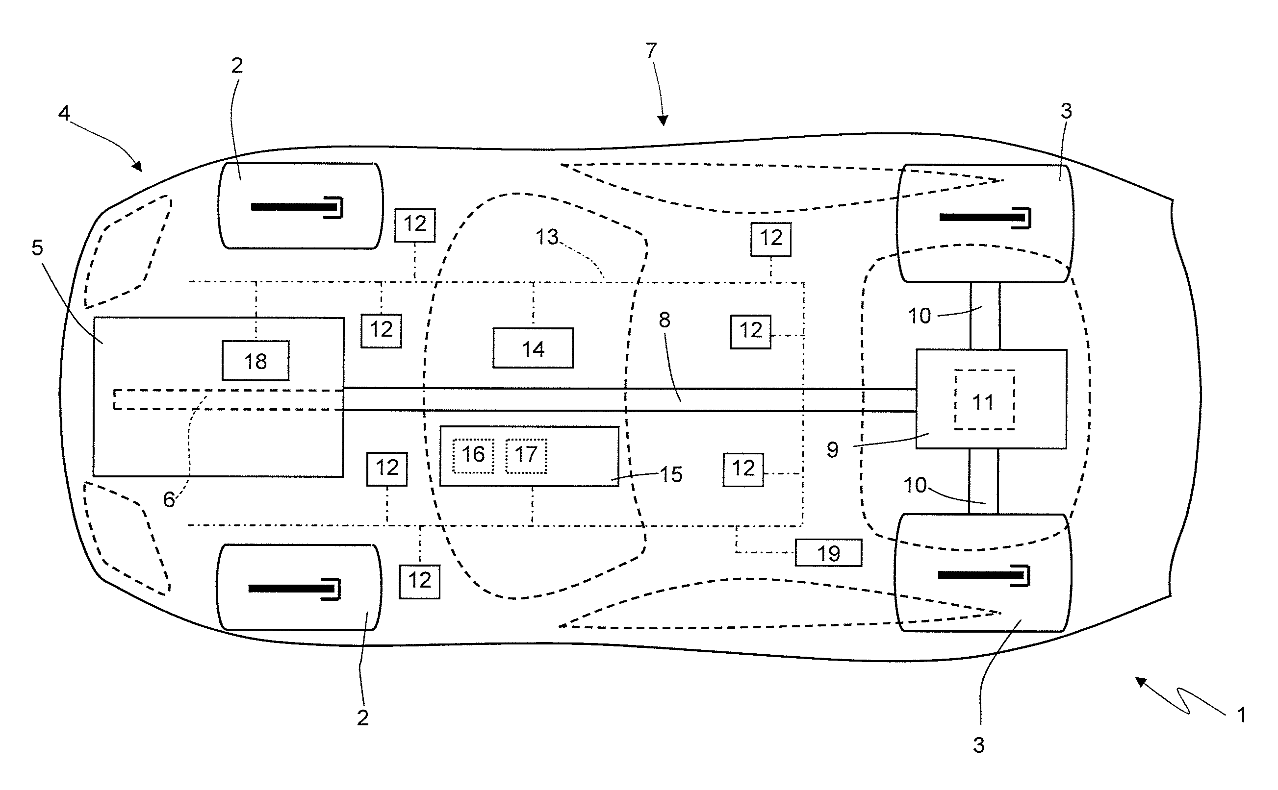
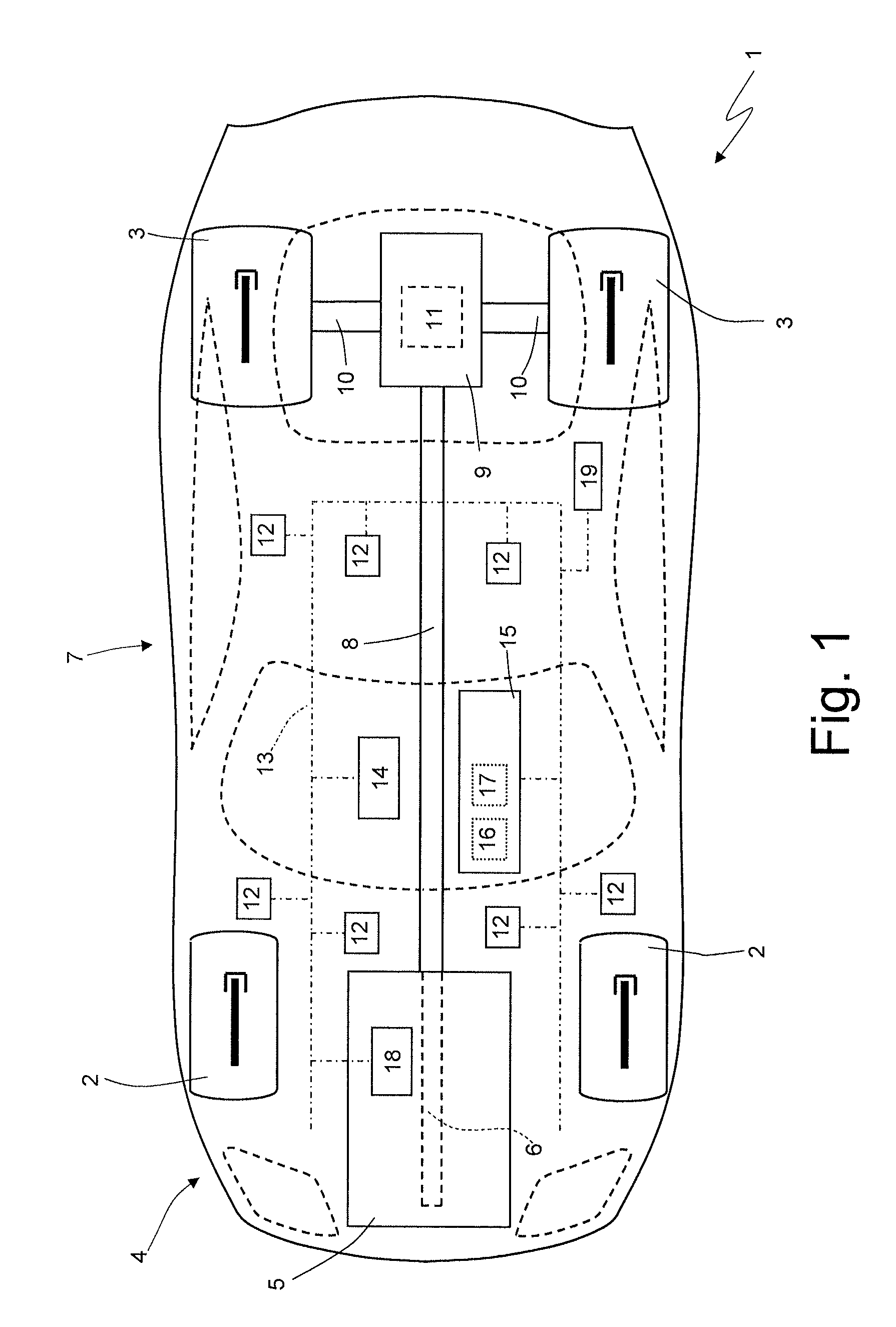
[0011]FIG. 1 shows a schematic of a road vehicle implementing the driver behaviour analysis method according to the present invention;

[0012]FIG. 2 shows a graph illustrating interpolation of a space-dependent pattern of a dynamic characteristic of the vehicle;

[0013]FIG. 3 shows a schematic of two possible vehicle paths between the same start and end points;

[0014]FIGS. 4-7 show graphs of space-dependent test patterns of two dynamic characteristics of the vehicle wh...


PUM


Abstract

A road vehicle (1) driver behavior analysis method, the analysis method including the steps of determining and memorizing the instantaneous position of the vehicle (1) expressed in geographic coordinates; determining and memorizing at least one dynamic characteristic characterizing motion of the vehicle (1); classifying a current road section just travelled by the vehicle (1); determining the space-dependent pattern of the dynamic characteristic along the current road section; determining a deviation between the space-dependent pattern of the dynamic characteristic along the current road section, and a space-dependent mean pattern or statistical distribution of the dynamic characteristic along the same or a similar road section and determined in previous runs of the vehicle (1); and identifying anomalous driver behavior if the absolute value of the deviation is above a given threshold.

Description

TECHNICAL FIELD[0001]The present invention relates to a road vehicle driver behaviour analysis method.BACKGROUND ART[0002]Driver distraction, indecision, and high speed are the major causes of road vehicle accidents.[0003]Modern road vehicles are equipped with numerous electronic controls which exchange information over an on-board BUS type data network known as a CAN (Car Area Network), which is supplied with the main dynamic data of the vehicle (i.e. longitudinal speed, individual wheel rotation speed, and longitudinal and lateral acceleration) and the commands imparted by the driver (i.e. steering angle, brake pressure, throttle position, engaged gear). An increasing number of vehicles are also equipped with a GPS receiver, which provides a fairly accurate, real-time georeference location of the vehicle.[0004]Various methods of determining road vehicle driver behaviour have been proposed based on statistical algorithms, which determine anomalous driving behaviour solely on the ba...

Claims


Application Information

Patent Timeline
Patent Type & Authority Patents(United States)
IPC IPC(8): G01M17/00
CPCB60W30/0953B60W40/09B60W50/14B60W2520/105B60W2520/125B60W2520/14B60W2520/28B60W2540/12B60W2550/402B60W2556/50B60W2540/18
Inventor BRIGHENTI, ATTILIOBIANCAT, JACOPO
Owner T E -SYST & ADVANCED TECH ENG
Learn More