
Cardiac event detection over varying time scale

a technology of event detection and time scale, applied in the field of cardiac event detection over varying time scale, can solve the problems of unreliable detection from a standard 12 lead ecg, ami is a common life-threatening complication, and the number of periodic biopsies of heart tissue as an indicator of transplant rejection can be greatly reduced, and the effect of restoring normal blood flow

Active Publication Date: 2012-08-14
ANGEL MEDICAL SYST
View PDF26 Cites 0 Cited by
  • Summary
  • Abstract
  • Description
  • Claims
  • Application Information

AI Technical Summary

Benefits of technology

Enables early intervention in coronary artery narrowing, reduces the frequency of costly and invasive biopsies, and provides timely alerts for potential heart attacks by monitoring changes in ST segment voltage and QRS complex voltage, thereby improving patient outcomes and reducing healthcare costs.

Problems solved by technology

AMI is a common and life-threatening complication of coronary artery disease.
Those with coronary atherosclerosis are at higher risk for AMI if the plaque becomes further obstructed by thrombus.
However, without knowing the patient's normal (i.e., baseline) ECG pattern, detection from a standard 12 lead ECG can be unreliable.
The Reveal also does not have the capability to measure ST segment shift.
In fact, its high pass filtering and electrode spacing preclude accurate detection of changes in the low frequency aspects of the heart's electrical signal, which low frequency aspects are required for the detection of ischemia.
While pacemakers track the numbers of beats paced or not paced and pacemaker programmers can display the beat data in histogram format, pacemakers do not produce histograms of heart signal parameters related to the electrogram wave form.
In other words, pacemakers track pacemaker operation but pacemakers do not measure or compute heart signal parameters of the beats in the electrogram signal, nor do they save the computed values of heart signal parameters in memory.
Unfortunately, pacemakers are not designed to collect weeks or months of statistical data on electrogram voltage variations.
The additional external support equipment needed to continually offload the raw electrogram data from a pacemaker is expensive and inconvenient to use.

Method used


Image

  • Cardiac event detection over varying time scale
  • Cardiac event detection over varying time scale
  • Cardiac event detection over varying time scale

Examples


Embodiment Construction

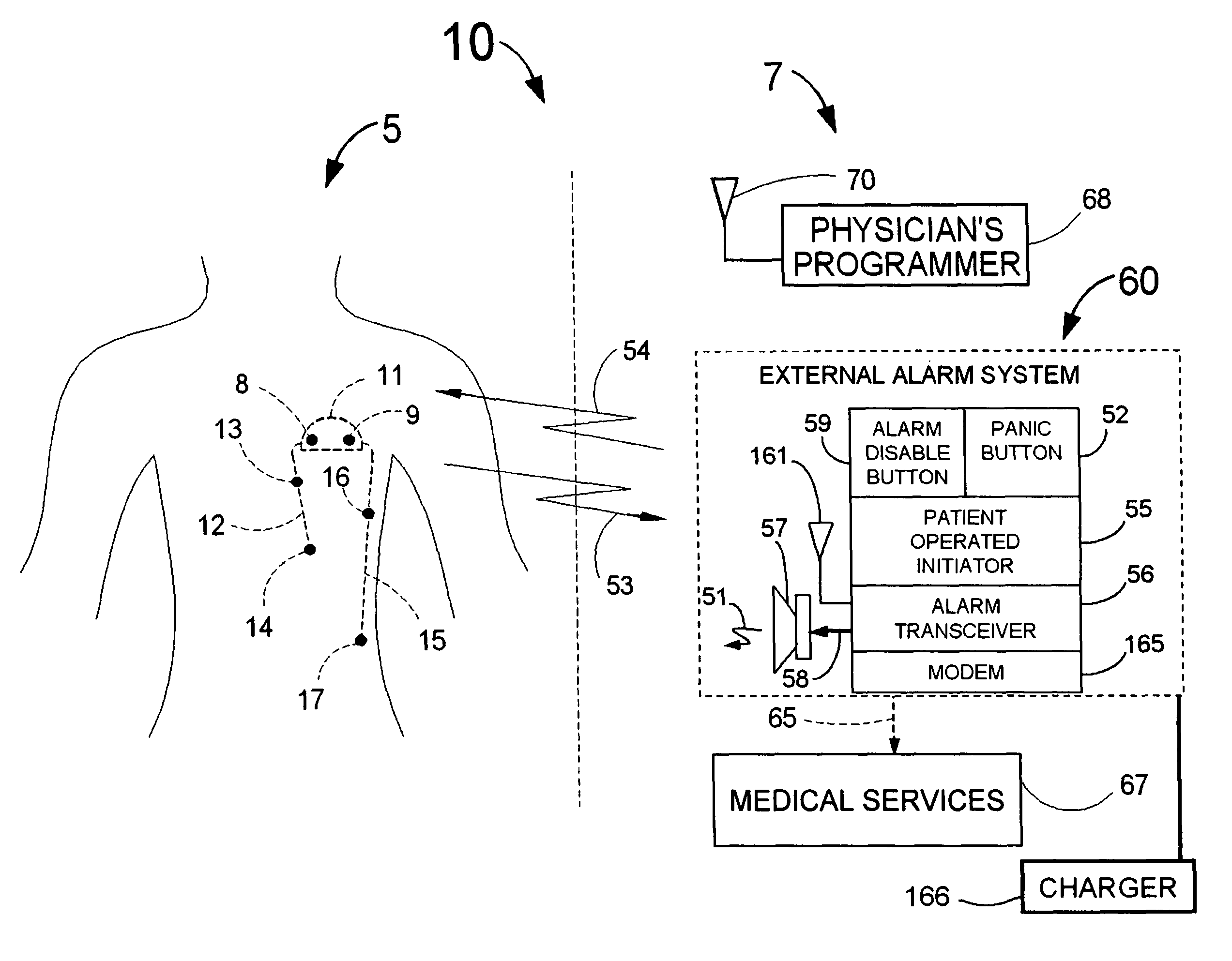
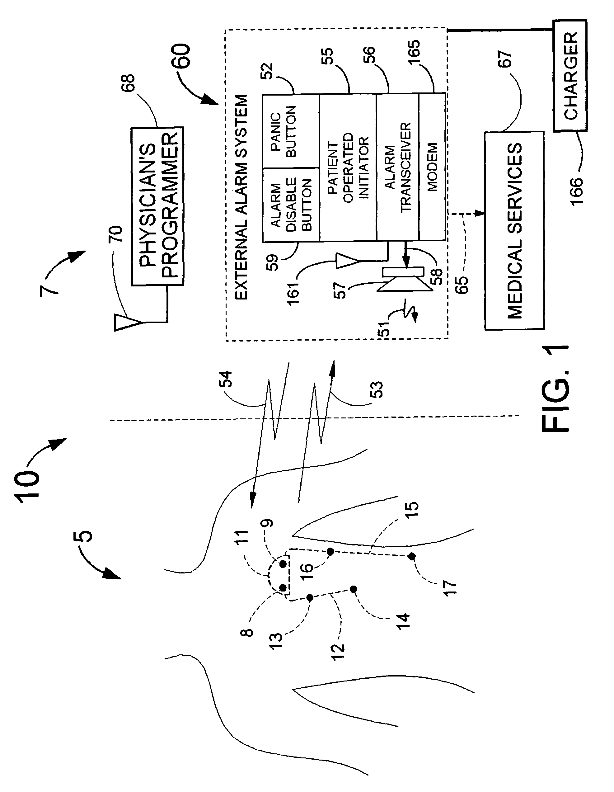
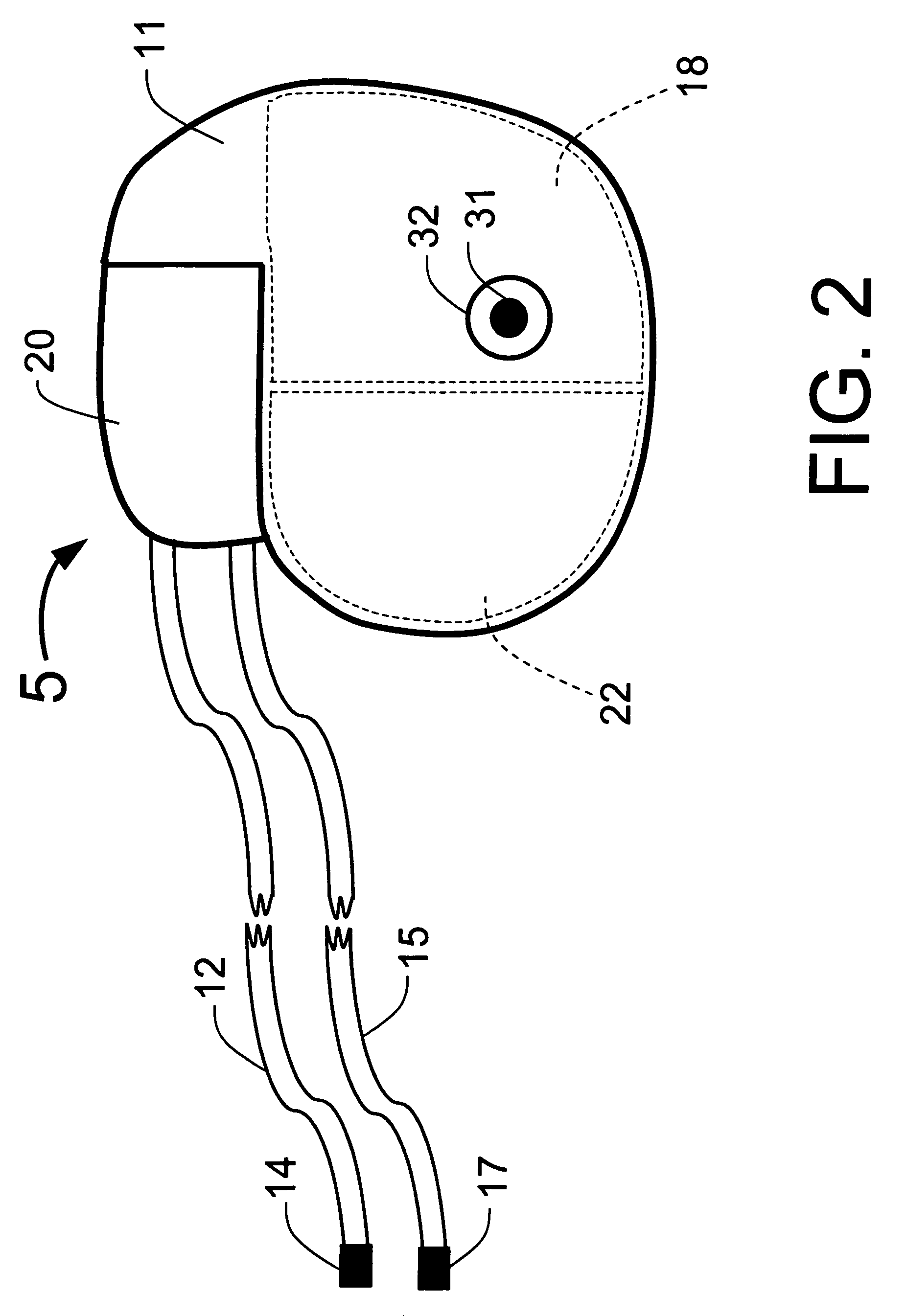
[0110]FIG. 1 illustrates an example of a tracker system 10 including an implanted cardiotracker 5 and external equipment 7. The cardiotracker 5 includes electrical wire leads 12 and 15 and a battery-powered electronics module contained within a metal case 11. The cardiotracker 5 can track the patient's cardiovascular condition over extended periods of time. The cardiotracker 5 can also detect acute cardiac events including acute myocardial infarction and arrhythmias and warn the patient when such an event occurs. The cardiotracker 5 can also track slowly changing cardiac functions such as day-to-day changes in QRS voltage that can be indicative of the rejection of a transplanted heart. The cardiotracker 5 can record the patient's electrogram signal for later review by a medical practitioner. The cardiotracker 5 can capture histogram-based historical representations of one or more heart signal parameters for later analysis and review by a medical practitioner. The cardiotracker 5 can...


PUM


Abstract

A system for cardiac event detection over varying time scales includes implanted electrical leads forming a portion of an implanted cardiotracker and external equipment including external alarm mechanisms and a physicians programmer. The cardiac event detection system monitors the degradation of a patient's cardiovascular condition from one or more causes. A processor computes the electrical signals of a heart signal parameter's average value over a time period for a multiplicity of heart rate ranges. The electrical signals are stored and information transmitted to external equipment.

Description

CROSS REFERENCE TO RELATED APPLICATIONS[0001]This application is a Continuation in part of patent application Ser. No. 10 / 950,401, now U.S. Pat. No. 7,512,438, filed on 28 Sep. 2004 which is a patent application based upon Provisional Patent Application Ser. No. 60 / 524,873, entitled “System for Monitoring Cardiovascular Condition” filed provisionally on 26 Nov. 2003.FIELD OF USE[0002]This invention is in the field of systems that monitor a patient's cardiovascular condition using implanted devices that interact with other devices located externally to the patient.BACKGROUND OF THE INVENTION[0003]Heart disease is the leading cause of death in the United States. A heart attack (also known as an acute myocardial infarction (AMI)) typically results from a thrombus (i.e., a blood clot) that obstructs blood flow in one or more coronary arteries. AMI is a common and life-threatening complication of coronary artery disease. Myocardial ischemia is caused by an insufficiency of oxygen to the ...

Claims


Application Information

Patent Timeline
Patent Type & Authority Patents(United States)
IPC IPC(8): A61B5/0402A61B5/366
CPCA61B5/0031A61B5/04012A61B5/0472A61B5/413A61N1/025A61N1/37211A61B5/686A61B5/044A61B5/0432A61B5/042A61B5/746A61B5/02455A61B5/02405A61B5/0006A61B5/0452A61N1/37247A61B5/349A61B5/366A61B5/339A61B5/358A61B5/33A61B5/329A61B5/29
Inventor FISCHELL, DAVID R.FISCHELL, ROBERT E.HARWOOD, JONATHANJOHNSON, STEVEN R.
Owner ANGEL MEDICAL SYST
Learn More