Magnetic flux controllable rotating electric machine system
a magnetic flux control and electric machine technology, applied in the direction of rotating magnets, synchronous machines with stationary armatures, windings, etc., can solve the problems of difficult control of electric motors, high-speed rotational regions, and inability to achieve optimal power in a wide rotational speed range, so as to increase the magnetic flux crossing the armature coil, and increase the magnetic resistance
- Summary
- Abstract
- Description
- Claims
- Application Information
AI Technical Summary
Benefits of technology
Problems solved by technology
Method used
Image
Examples
first embodiment
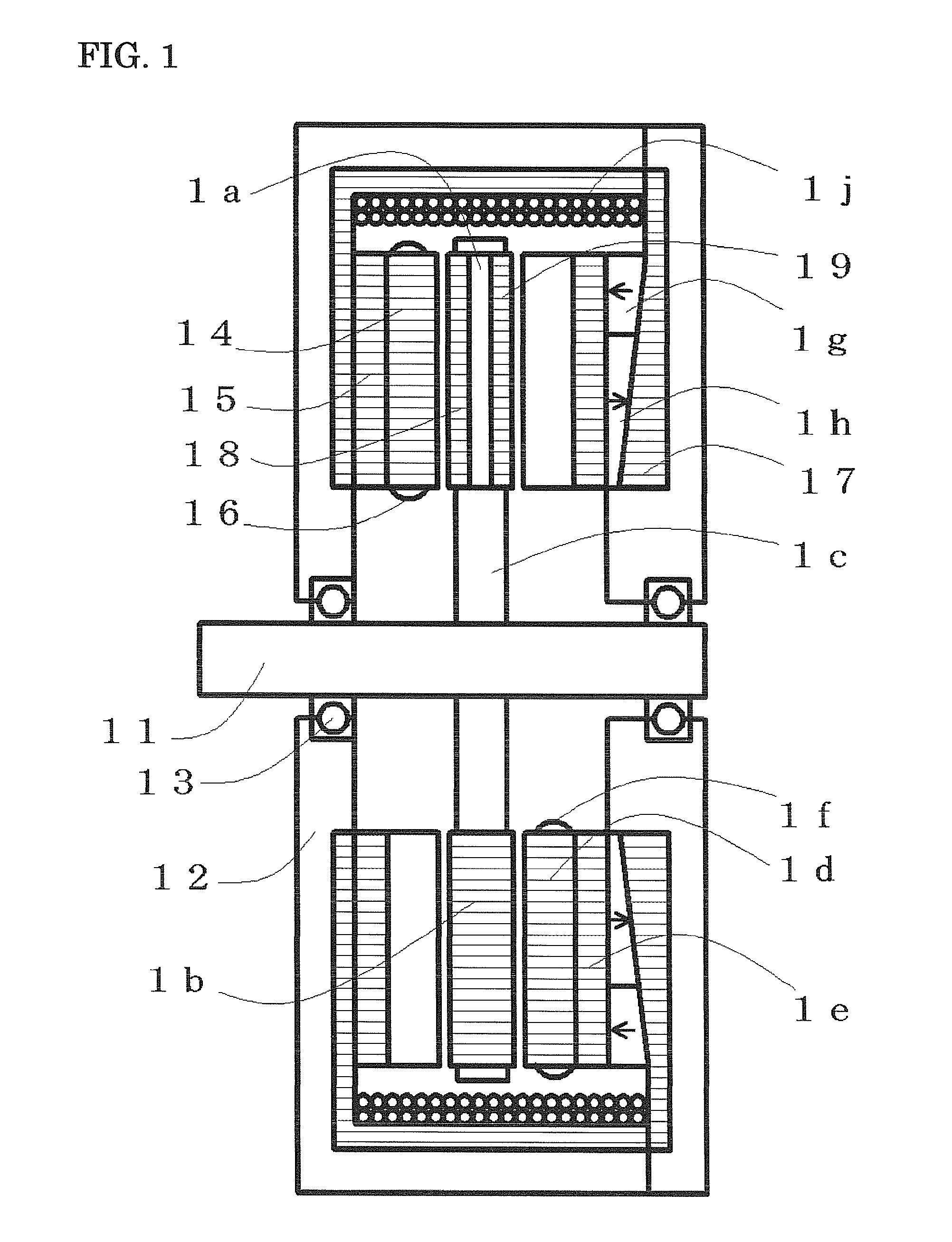
[0097]FIG. 6 shows a longitudinal sectional view of the embodiment in which the present invention is applied to a rotating electric machine apparatus having an axial gap structure, double stators. Although rotor composition is almost the same as the first embodiment shown in FIG. 1, a permanent magnet 62 is disposed between the island-shaped magnetic poles 18 and 19, and a permanent magnet 65 is disposed between the magnetic salient poles 64 and 66. Thickness of the permanent magnet 65 is smaller than that of the permanent magnet 62. Arrows in the permanent magnets 62 and 65 indicate magnetization direction. The permanent magnet magnetizes the island-shaped magnetic poles 18 and 19 while being an isolation member between the island-shaped magnetic poles 18 and 19, the permanent magnet 65 magnetizes the magnetic salient poles 64 and 66 while being an isolation member between the magnetic salient poles 64 and 66.
[0098]As viewed in FIG. 6, the first armature disposed at left side has a...
fourth embodiment
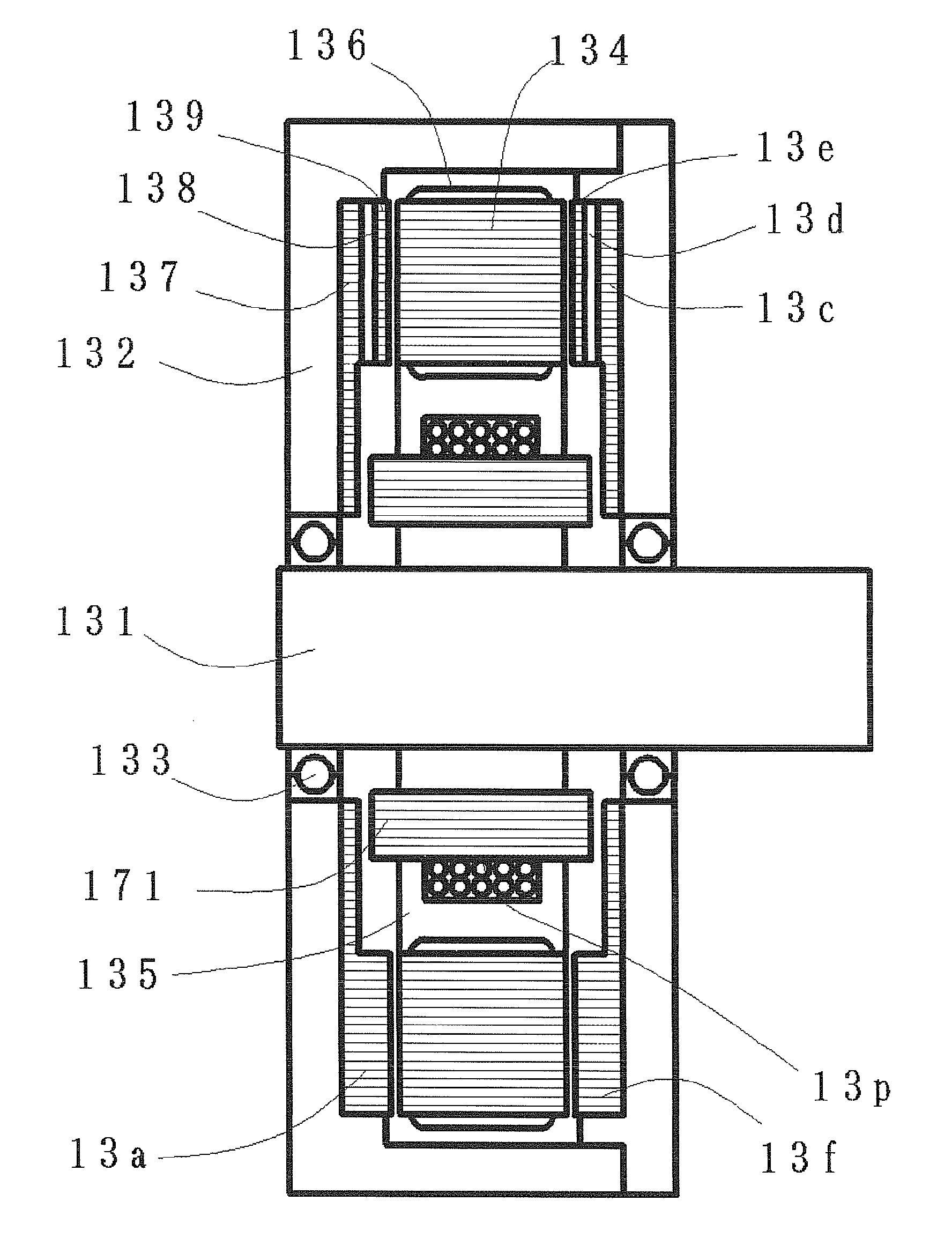
[0184]An armature and a rotor of a rotating electric machine showing a longitudinal section in FIG. 17 are same as the rotating electric machine of the fourth embodiment shown in FIG. 13 except a magnetic excitation part, and the magnetic excitation part is electric current excitation. The magnetic excitation part consists of the cylindrical magnetic core 171 that is an excitation flux path member, the excitation coil 13p wound around the cylindrical magnetic core 171, and both ends of the cylindrical magnetic core 171 face prolonged parts of the circular magnetic substrates 137 and 13c, respectively. Magnetic flux induced by the excitation coil 13p flows through the cylindrical magnetic core 171, the circular magnetic substrate 137, the magnetic salient poles 13a, the magnetic teeth 134, the magnetic salient poles 13f, and the circular magnetic substrate 13c, then flux amount through the armature coil 136 is controlled effectually.
[0185]Although composition of the armature and the ...
third embodiment
[0203]The magnetic excitation part is the same composition as the third embodiment, an excitation path pole 9k faces the magnetic core 239 connecting with a circular magnetic substrate of the first rotor 234 through a minute gap, an excitation path pole 9m faces the magnetic core 23a connecting with a circular magnetic substrate of the second rotor 238 through a minute gap. The cylindrical first magnet element 9p and the second magnet element 9n are arranged between the cylindrical excitation path poles 9k and 9m, the excitation coil 9q is arranged so that magnetic flux may be induced in closed magnetic path constituted from the excitation path pole 9m, the first magnet element 9p, the excitation path pole 9k, and the second magnet element 9n. Number 9r indicates a conductor layer.
[0204]Magnetic flux coming from the magnetic excitation part is supplied between the circular magnetic substrate of the first rotor 234 disposed at the left end, and the circular magnetic substrate of the ...
PUM
 Abstract
Description
Claims
Application Information
 - R&D
- Intellectual Property
- Life Sciences
- Materials
- Tech Scout
- Unparalleled Data Quality
- Higher Quality Content
- 60% Fewer Hallucinations
Browse by: Latest US Patents, China's latest patents, Technical Efficacy Thesaurus, Application Domain, Technology Topic, Popular Technical Reports.
© 2025 PatSnap. All rights reserved.Legal|Privacy policy|Modern Slavery Act Transparency Statement|Sitemap|About US| Contact US: help@patsnap.com


