
Probe connector

a technology of probe connectors and connectors, applied in the direction of incorrect coupling prevention, coupling device connection, electrical apparatus, etc., can solve the problem of wrong connection between the probe connectors, and achieve the effect of better electrical connection

Inactive Publication Date: 2012-08-14
CHENG UEI PRECISION IND CO LTD
View PDF8 Cites 46 Cited by
  • Summary
  • Abstract
  • Description
  • Claims
  • Application Information

AI Technical Summary

Benefits of technology

[0006]As described above, in use, the upper cover and the lower cover of the foolproof mechanism having different magnetism can effectively guide the probe connector to be mated with the mated connector based on the principle of homopolar repulsion and heteropolar attraction, because of corresponding two portions of the mated connector being provided with different magnetism. So, it can avoid the wrong connection between the probe connector and the mated connector, and a better electrical connection is assured.

Problems solved by technology

However, when the probe connector is engaged with a mated connector, it's apt to cause a wrong connection between the probe connector and the mated connector because of no identification mechanism for a correct mated position.

Method used


Image

  • Probe connector
  • Probe connector
  • Probe connector

Examples


Embodiment Construction

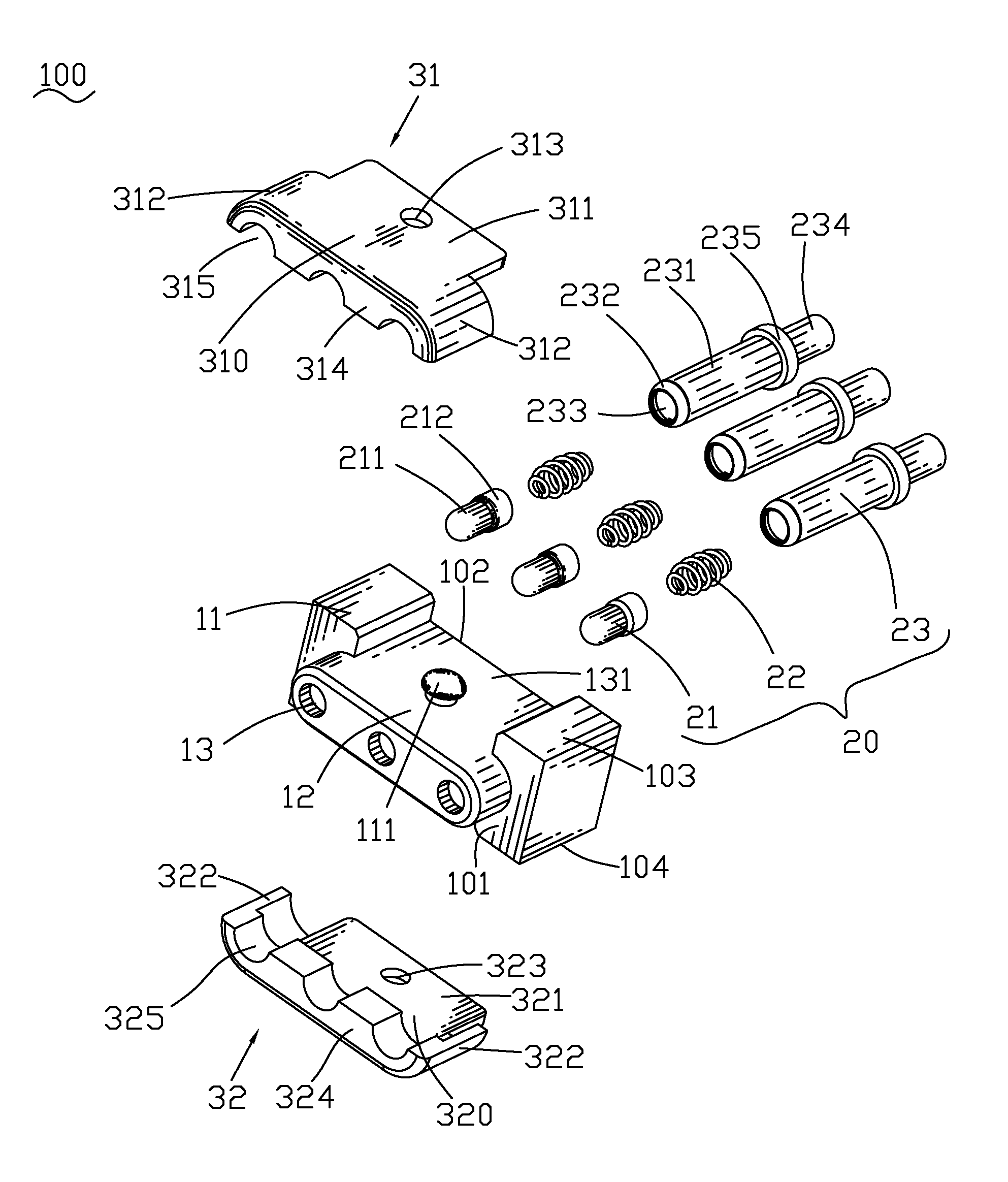
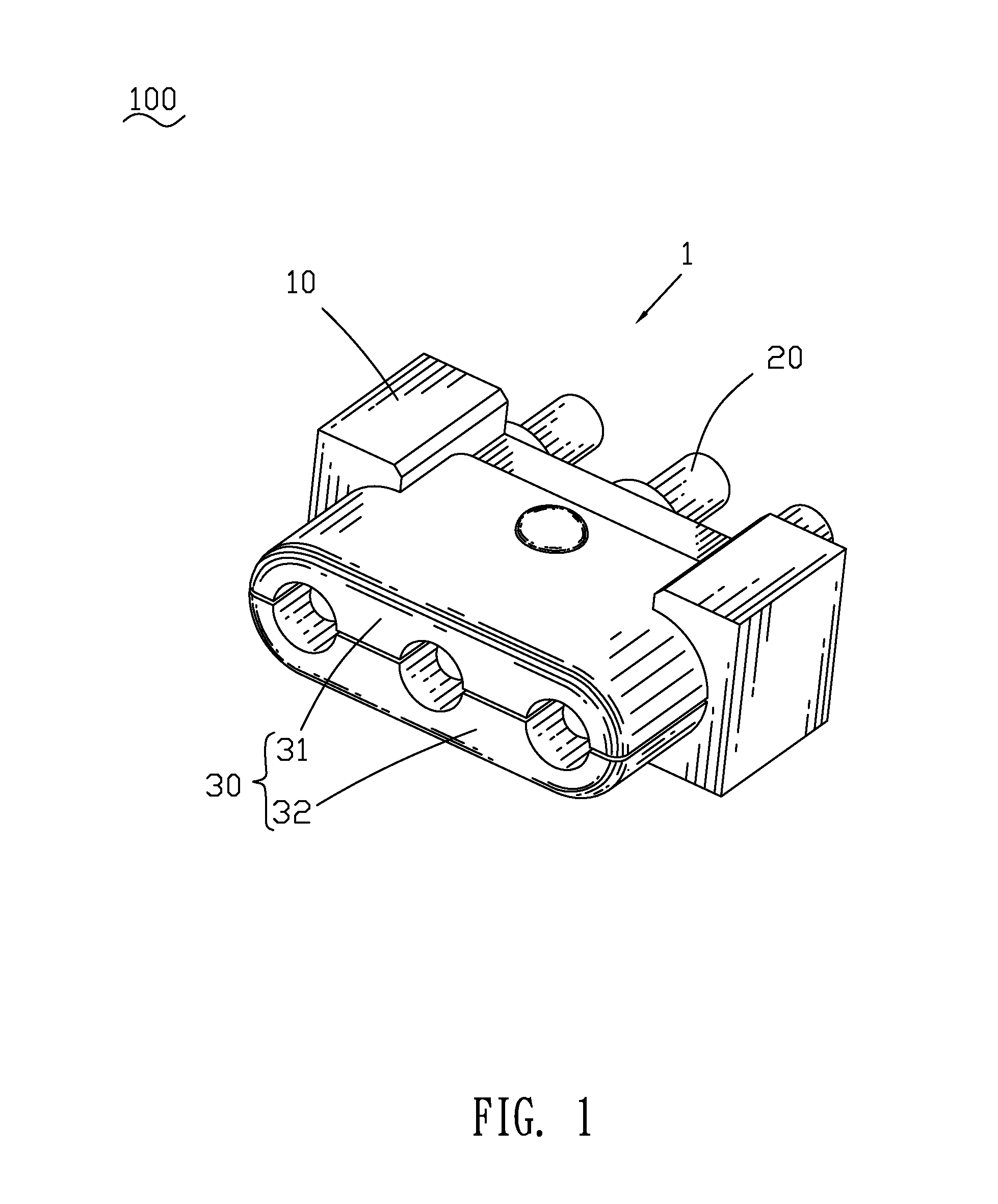
[0012]With reference to FIG. 1, a probe connector 100 according to the present invention includes an insulating housing 10, a plurality of probe pins 20 and a foolproof mechanism 30 mounted to the insulating housing 10 respectively.

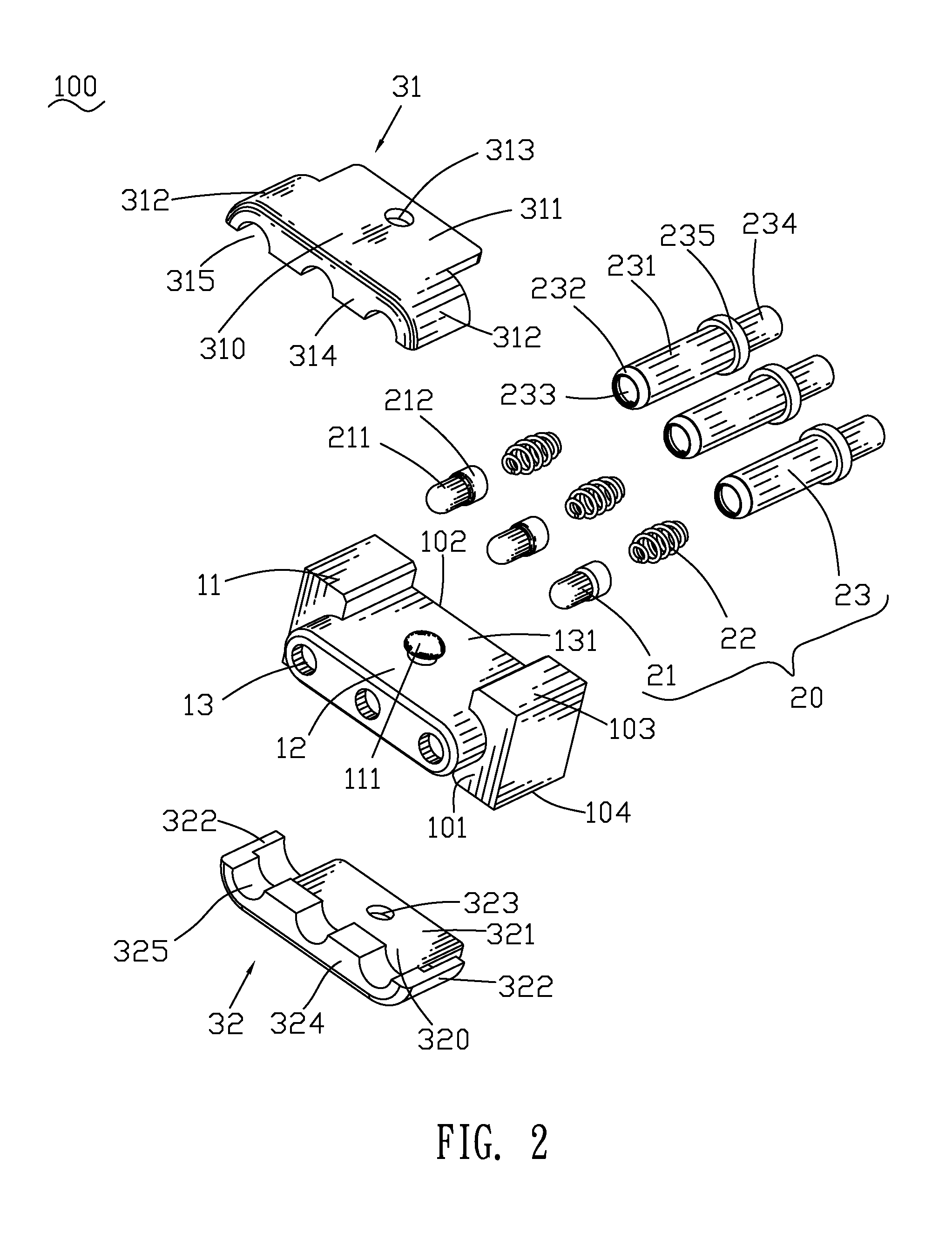
[0013]Referring to FIGS. 2-3, the insulating housing 10 has a base body 11 of rectangular shape. The base body 11 has a front surface 101, a rear surface 102, a top surface 103 and a bottom surface 104. A middle of the front surface 101 of the base body 11 protrudes frontward to form a tongue portion 12 of an elliptic shape seen from a front view. The insulating housing 10 defines a plurality of inserting holes 13 longitudinally penetrating through the base body 11 and the tongue portion 12. Middles of the top surface 103 and the bottom surface 104 are cut off to define a first opening 131 and a second opening 141 passing through the front surface 101 and the rear surface 102 of the base body 11. A first fastening portion 111 and a second fastening portio...


PUM


Abstract

A probe connector adapted for electrically interconnecting with a mated connector which has two portions thereof provided with different magnetism selected from a south magnetic pole and a north magnetic pole respectively, includes an insulating housing, a plurality of probe pins and a foolproof mechanism. The insulating housing defines a plurality of inserting holes penetrating therethrough for receiving the probe pins. The foolproof mechanism is made of magnetic material and includes an upper cover and a lower cover which have different magnetism selected from a north magnetic pole and a south magnetic pole respectively. The upper cover and the lower cover are mounted to two opposite sides of the insulating housing. The probe connector can be interconnected with the mated connector based on principles of homopolar repulsion and heteropolar attraction between the upper cover and the lower cover and the two portions of the mated connector.

Description

BACKGROUND OF THE INVENTION[0001]1. Field of the Invention[0002]The present invention relates to a probe connector, and more particularly to a probe connector capable of being effectively interconnected with a mated connector.[0003]2. The Related Art[0004]A traditional probe connector generally includes an insulating housing and a plurality of probe pins. The insulating housing has a front surface. The front surface defines a plurality of inserting holes spaced at regular intervals, and each of the inserting holes penetrates through the insulating housing along a front-to-rear direction. The probe pins are inserted in the inserting holes respectively. However, when the probe connector is engaged with a mated connector, it's apt to cause a wrong connection between the probe connector and the mated connector because of no identification mechanism for a correct mated position.SUMMARY OF THE INVENTION[0005]An object of the present invention is to provide a probe connector adapted for el...

Claims


Application Information

Patent Timeline
IPC IPC(8): H01R11/30
CPCH01R13/6205H01R13/64H01R13/2421
Inventor LIN, JUI-PIN
Owner CHENG UEI PRECISION IND CO LTD
Learn More