
Method and apparatus for distortion correction and image enhancing of a vehicle rear viewing system

a rear viewing system and distortion correction technology, applied in the field of vehicle rear viewing system, can solve the problems of inability to see objects behind the vehicle, frustrating and difficult task of driving a motor vehicle in reverse, and popular sport utility vehicle (“suv”) suffers from an even higher degree of difficulty in seeing during an attempt to travel in reverse, so as to enhance the pixels located in the captured images, enhance the captured image, enhance the effect of an imag

Active Publication Date: 2012-07-31
TRW AUTOMOTIVE US LLC
View PDF20 Cites 143 Cited by
  • Summary
  • Abstract
  • Description
  • Claims
  • Application Information

AI Technical Summary

Problems solved by technology

Operating a motor vehicle in reverse can be a frustrating and difficult task.
These frustrations largely result from a drivers' inability to see objects behind the vehicle while proceeding in reverse despite rearview mirrors and windows.
The increasing popular sport utility vehicle (“SUV”) suffers from an even higher degree of difficulty in seeing during an attempt to travel in reverse as compared to a passenger vehicle.

Method used


Image

  • Method and apparatus for distortion correction and image enhancing of a vehicle rear viewing system
  • Method and apparatus for distortion correction and image enhancing of a vehicle rear viewing system
  • Method and apparatus for distortion correction and image enhancing of a vehicle rear viewing system

Examples


Embodiment Construction

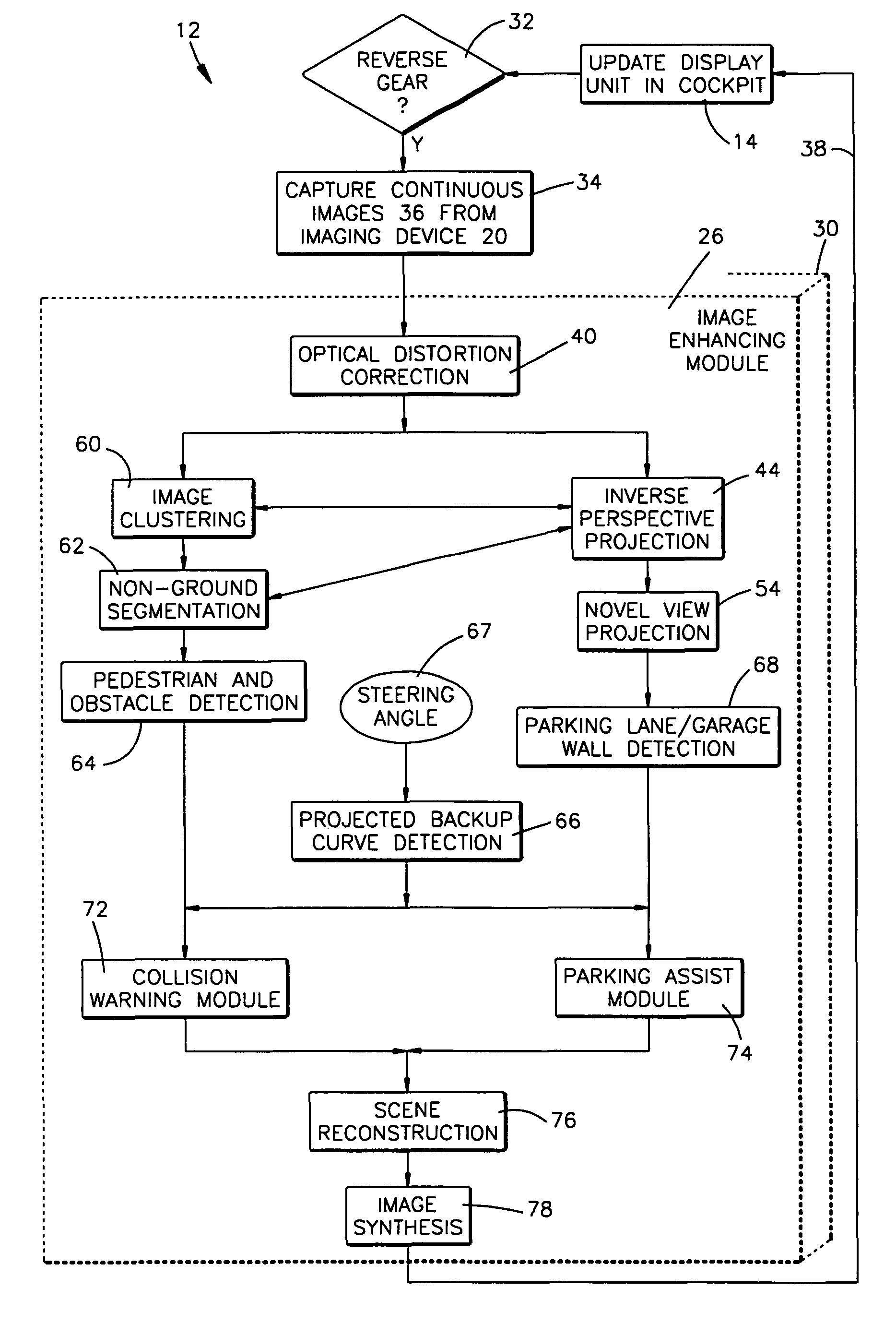
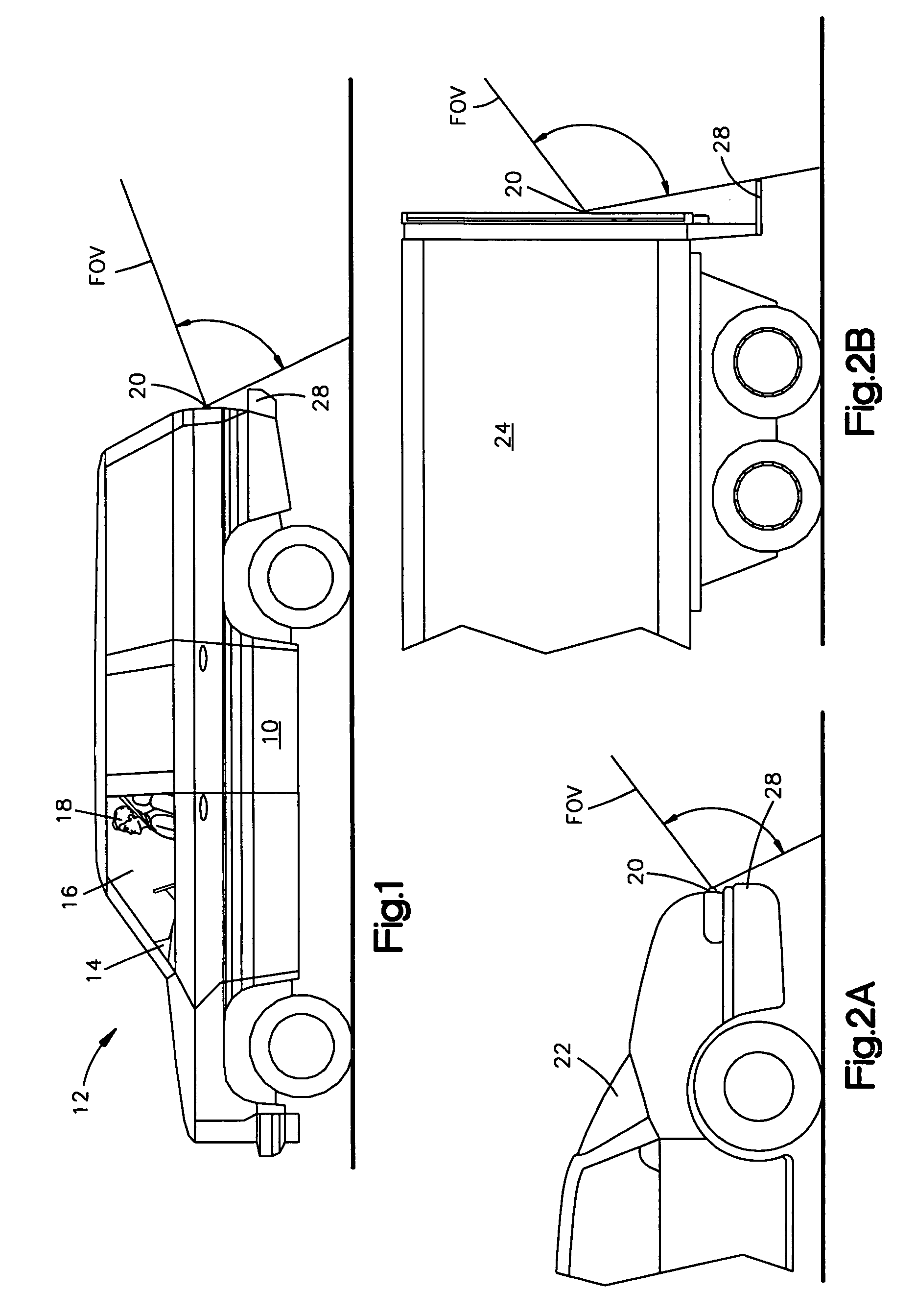
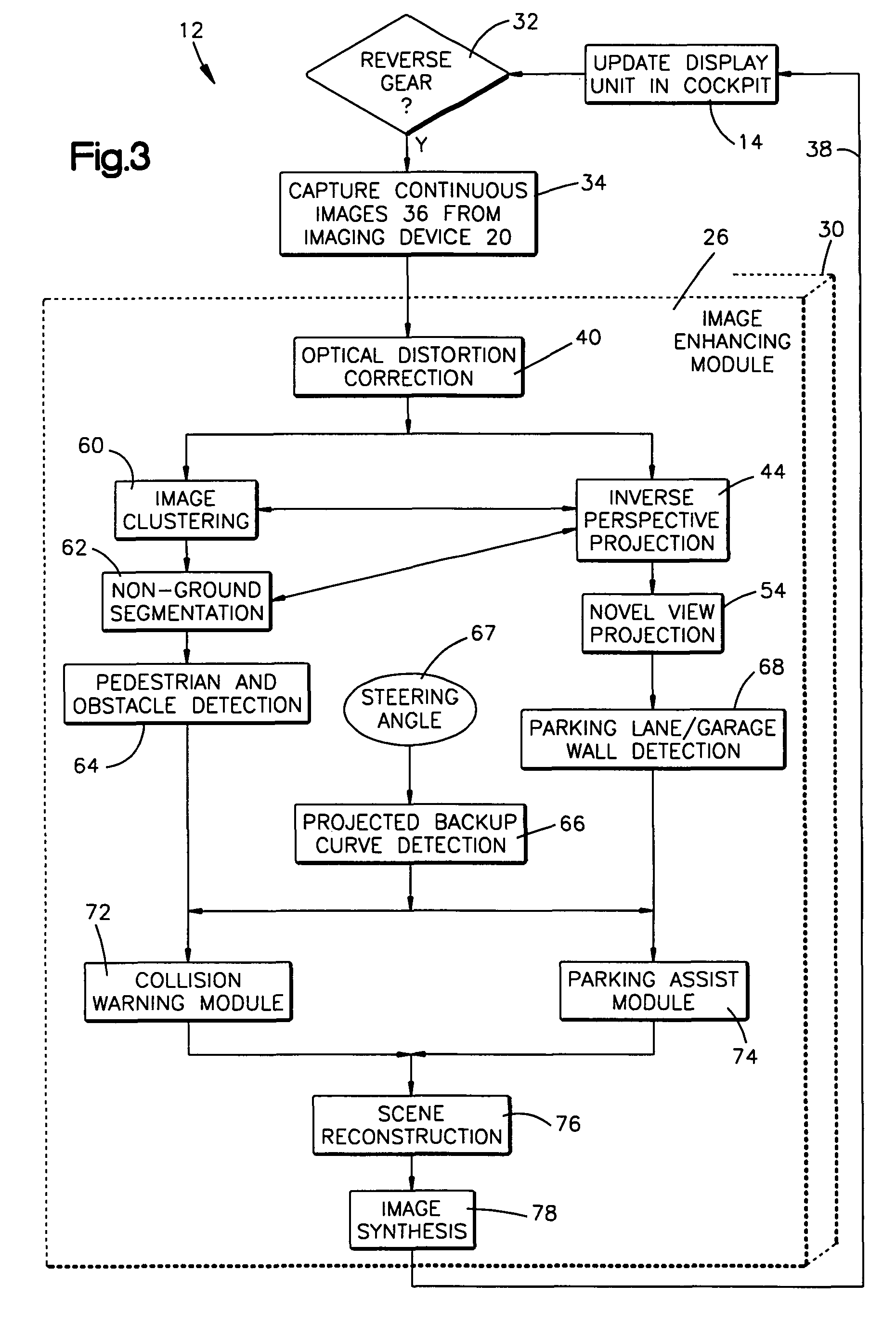
[0021]Referring to FIG. 1, a vehicle 10 includes a rearview distortion correcting and image “DCIE” enhancing system 12, in accordance with one example embodiment of the present invention, a display unit 14 located in the vehicle cabin 16 for viewing by the vehicle operator 18. The rearview DCIE system 12 provides real-time, wide angle video images to the operator 18 of the area behind the vehicle 10 through an imaging device 20. The imaging device 20 includes, for example a camera utilizing charge-coupled device (“CCD”) or complementary metal oxide semiconductor (“CMOS”) sensor technology for capturing a real-time continuous images illustrated as a field-of-view (“FOV”) of the imaging device 20.

[0022]While FIG. 1 illustrates the rearview DCIE system 12 being adapted to a sport utility type vehicle (SUV), FIGS. 2A and 2B illustrate that the system could also be adapted to a passenger vehicle 22, cargo transport vehicle 24, or any other type of movable vehicles or equipment such as fo...


PUM


Abstract

An image enhancing system for a vehicle comprises a display unit for displaying modified images and an imaging device for receiving captured images—enhanced by the image enhancing system. The system further includes an image enhancing module in communication with the display unit and the imaging device—such that pixels located in the captured images are enhanced by repositioning the pixels from a first position to a second position via a transfer operation.

Description

TECHNICAL FIELD[0001]The present invention is directed to a vehicle rear viewing system and more particularly, to a method and apparatus for distortion correction and image enhancing of a vehicle rear viewing system.BACKGROUND OF THE INVENTION[0002]Operating a motor vehicle in reverse can be a frustrating and difficult task. These frustrations largely result from a drivers' inability to see objects behind the vehicle while proceeding in reverse despite rearview mirrors and windows. The areas blocked from a driver's view are the result of the vehicle structure due to dead angle areas hidden from view through the vehicles' mirrors (referred to as blind spots), and because of other causes.[0003]The increasing popular sport utility vehicle (“SUV”) suffers from an even higher degree of difficulty in seeing during an attempt to travel in reverse as compared to a passenger vehicle. To aid the driver in becoming more aware of the surroundings behind the SUV, rearview camera systems have bee...

Claims


Application Information

Patent Timeline
Patent Type & Authority Patents(United States)
IPC IPC(8): H04N7/18H04N9/47B60R1/06G06T5/00H04N5/21H04N5/335
CPCB60Q9/005G06T5/006
Inventor LUO, YUNST. JOHN, CHRISPRAINITO, JOHN
Owner TRW AUTOMOTIVE US LLC
Learn More