
Engine starting device

a technology of engine starting and starting device, which is applied in the direction of engine starting device, electric control, instruments, etc., can solve the problems of increasing the frequency of radiation noise and increasing the current consumption, and affecting the operation of the engin

Active Publication Date: 2012-07-24
OMRON AUTOMOTIVE ELECTRONICS CO LTD
View PDF18 Cites 28 Cited by
  • Summary
  • Abstract
  • Description
  • Claims
  • Application Information

AI Technical Summary

Benefits of technology

"The present invention provides an engine starting device that can reliably start an engine even when the battery output voltage is lower than usual. The device includes a control processing unit and a step-up circuit for increasing the battery output voltage. The step-up circuit is designed to activate only when necessary to prevent breakdown or reset of the control processing unit. The device also minimizes the negative effects of radiation noise and increased current consumption during the step-up operation. Overall, the device ensures high reliability and minimizes the impact of the battery output voltage on the engine start-up process."

Problems solved by technology

Thus, the extent and the frequency of the step-up operation that is unnecessarily performed other than in time of the engine start due to the lowering of the battery output voltage increase, thereby causing large negative effects from practical standpoint.
That is, when the step-up operation by the step-up circuit is performed, the radiation noise occurs as an oscillation circuit in the step-up circuit is activated, and current consumption obviously increases.
The extent and the occurrence frequency of the radiation noise and the increase in current consumption obviously increase the higher the step-up start voltage is set.
However, when the battery output voltage becomes lower than the minimum operation voltage of the starter relay in time of the engine start, the control unit activates, but the starter relay does not activate, and the engine cannot be started.

Method used


Image

  • Engine starting device
  • Engine starting device
  • Engine starting device

Examples


first example

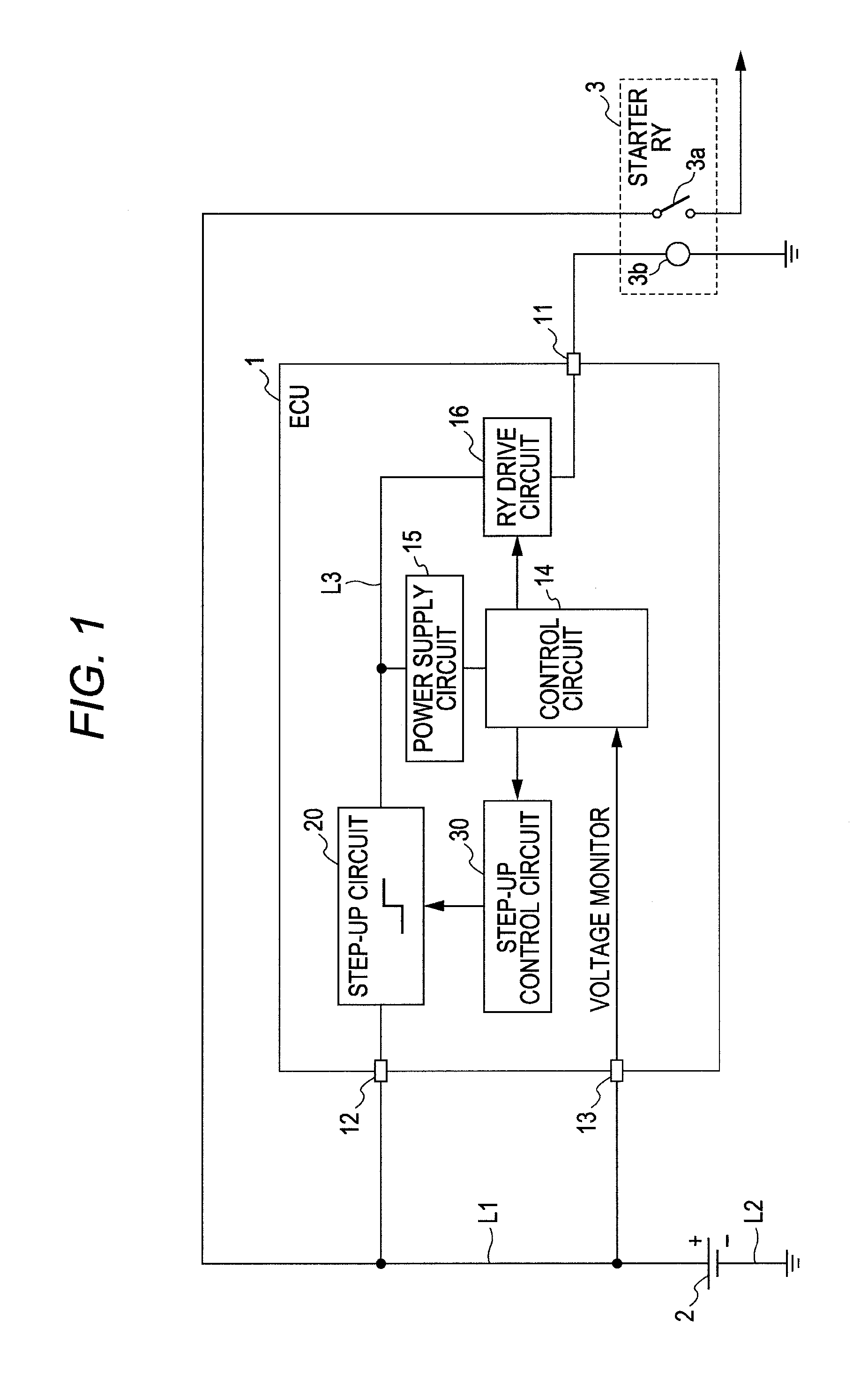
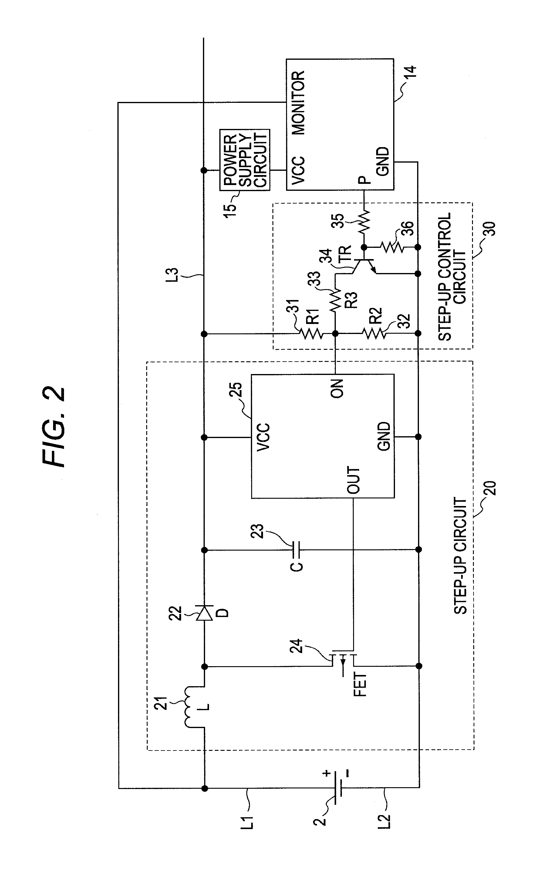
[0025]First, a first example will be described. FIG. 1 is a circuit diagram showing an overall configuration of an engine starting device of the present example. FIG. 2 is a circuit diagram showing a detailed configuration of main parts of the engine starting device.

[0026]Reference number 1 in FIG. 1 is a control unit (ECU) for engine start. In the present example, the control unit 1 corresponds to the engine starting device according to one or more embodiments of the present invention, and incorporates a step-up circuit 20 and a step-up control circuit 30, to be hereinafter described. The step-up circuit 20, and the like to be hereinafter described may be arranged as a separate unit at the exterior of the control unit 1, and the engine starting device according to one or more embodiments of the present invention may be configured with all of the above. In the present example, a mode in which the step-up circuit 20 and the like are incorporated in the control unit 1 is illustrated.

[...

second example

[0070]The second example will be described below. This example is a mode in which the step-up start voltage is unconditionally switched to the second voltage value in time of the engine start without monitoring the output voltage of the battery 2. FIG. 5 shows the processing procedure (flowchart) of the control circuit 14 for this case. In FIG. 5, step S2 in FIG. 4 is omitted, and the processing contents of other steps are the same as in FIG. 4. However, if the determination result of step S1 is positive, the process proceeds to step S3. The circuit configuration of the present example may be similar to the first example. However, since the output voltage of the battery 2 is not monitored, the MONITOR terminal of the control circuit 14 shown in FIG. 2 can be omitted in the present example.

[0071]In the case of the present example, the step-up start voltage is unconditionally switched to the second voltage value when the engine starting condition is satisfied. Thus, if the output volt...


PUM


Abstract

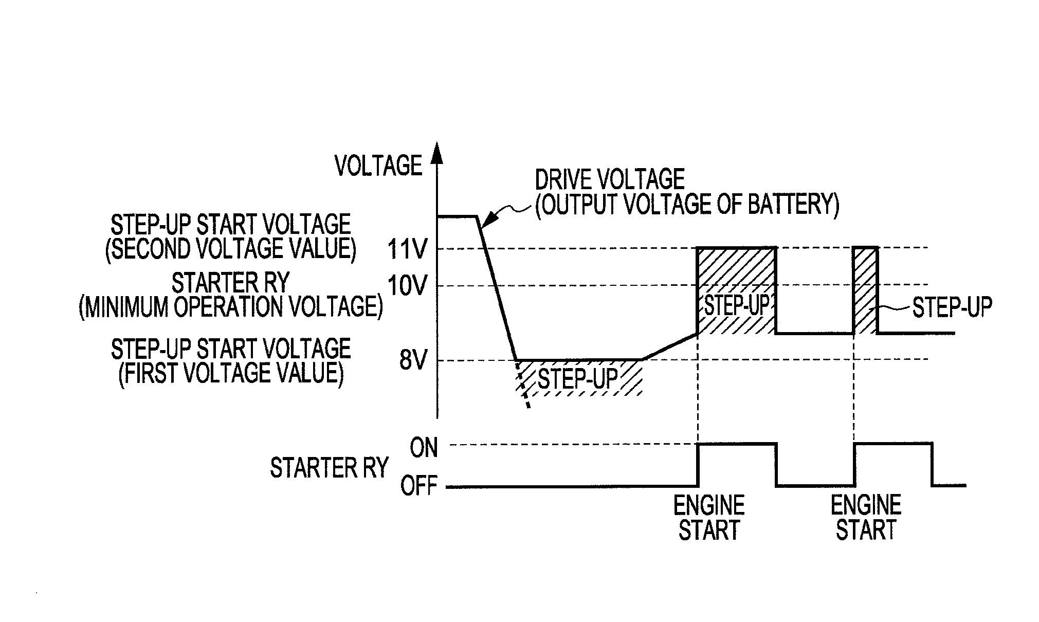
An engine starting device for controlling an engine start of a vehicle by driving a starter relay of the vehicle with a battery of the vehicle as a power supply has a control processing unit and a step-up circuit for stepping up the output of the battery and outputting a drive voltage for driving the control processing unit and the starter relay. The control processing unit has a function of performing an engine start control of applying the drive voltage to the starter relay to activate the starter relay in time of the engine start at which an engine starting condition is satisfied The control processing unit performs a control function on the step-up circuit to activate the step-up circuit so that the drive voltage does not become lower than a minimum operation voltage of the starter relay in a predetermined period necessary to start the engine in time of the engine start, and activate the step-up circuit so that the drive voltage does not become lower than a first voltage value higher than a minimum operation voltage of the control processing unit and lower than the minimum operation voltage of the starter relay when not in the predetermined period.

Description

BACKGROUND OF THE INVENTION[0001]1. Technical Field[0002]The present invention relates to an engine starting device capable of starting an engine of a vehicle at high reliability even in time of lowering of a battery output voltage.[0003]2. Related Art[0004]Conventionally, there are known a technique of arranging a step-up circuit for stepping up battery output of a vehicle to prevent drawbacks such as a main control unit (ECU; Electrical Control Unit) in the vehicle from being reset due to lowering of a battery voltage when starting an engine as described in Japanese Unexamined Patent Publication No. 2005-218159, and a technique of arranging a step-up circuit so that an engine can be started even in a kick method in a full track two-wheeled vehicle engine starting device as described in Japanese Unexamined Patent Publication No. 2004-36494.[0005]In order to enhance the reliability of engine start in a vehicle equipped with an engine (internal combustion engine) as a drive source su...

Claims


Application Information

Patent Timeline
Patent Type & Authority Patents(United States)
IPC IPC(8): G06F19/00
CPCF02N11/0862F02D2041/2003F02N11/0848F02N2011/0888F02N2200/043F02N2200/063F02N2250/02
Inventor IKUSHIMA, YOSHIHIROKINBARA, KENICHI
Owner OMRON AUTOMOTIVE ELECTRONICS CO LTD
Learn More