
Systems and methods to improve clarity in ultrasound images

a technology of ultrasound image and clarity, applied in image enhancement, instruments, applications, etc., can solve the problems of inability to achieve the effect of preserving shape and volume, improving ultrasound communication, and facilitating container refilling

Inactive Publication Date: 2012-07-17
VERATHON
View PDF246 Cites 58 Cited by
  • Summary
  • Abstract
  • Description
  • Claims
  • Application Information

AI Technical Summary

Benefits of technology

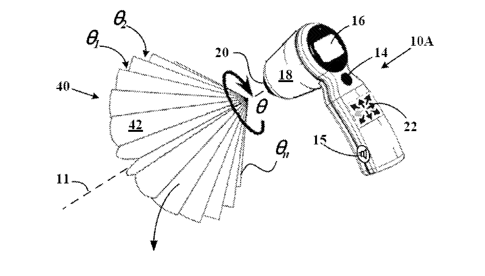
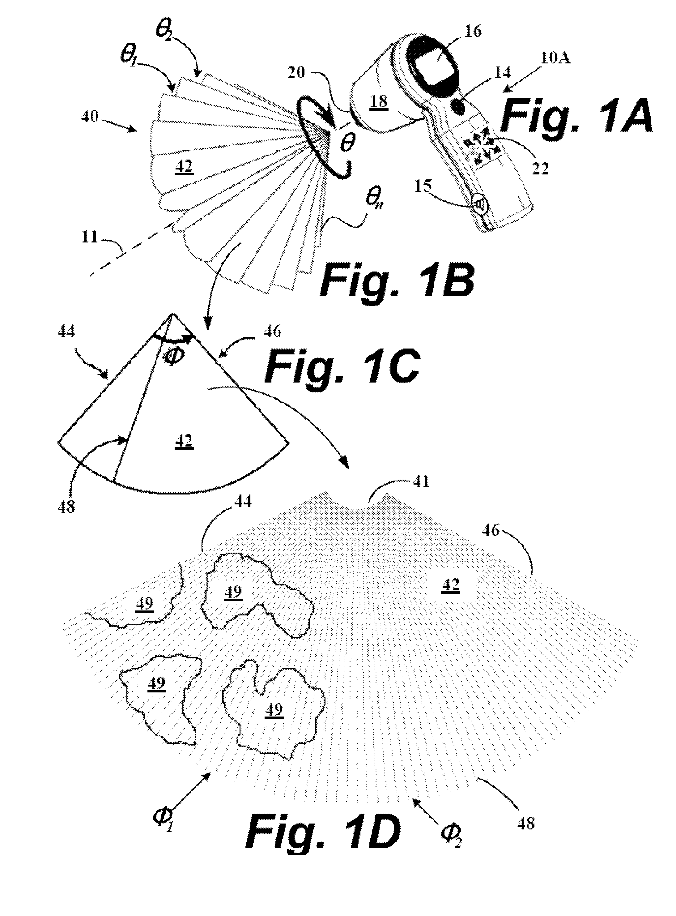
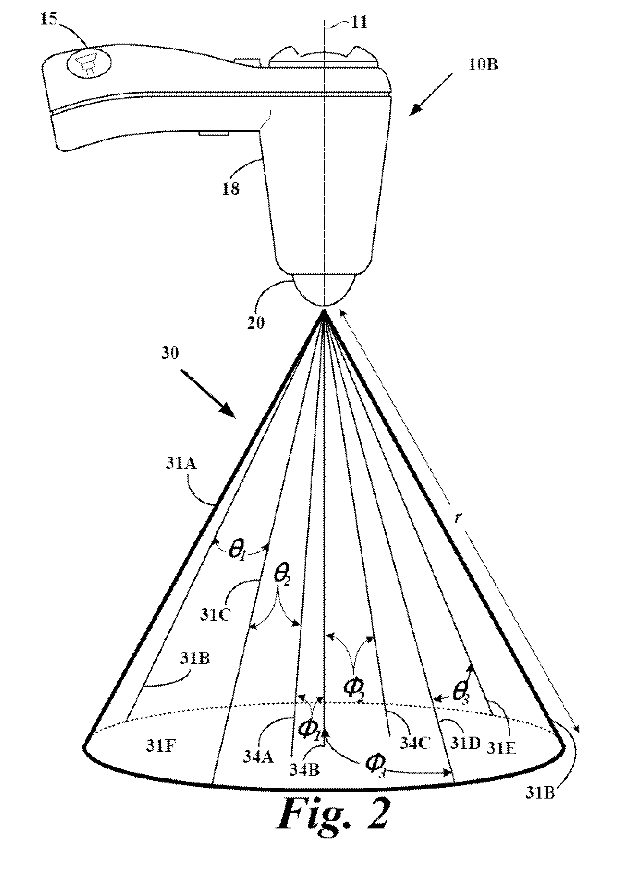
[0023]Systems, methods, and devices for image clarity of ultrasound-based images are described. Such systems, methods, and devices include improved transducer aiming and utilizing time-domain deconvolution processes upon the non-stationary effects of ultrasound signals. The processes deconvolution applies algorithms to improve the clarity or resolution of ultrasonic images by suppressed reverberation of ultrasound echoes. The initially acquired and distorted ultrasound image is reconstructed to a clearer image by countering the effect of distortion operators. An improved point spread function (PSF) of the imaging system is applied, utilizing a deconvolution algorithm, to improve the image resolution, and remove reverberations by modeling them as noise.
[0027]As regards sonic coupling gel media to improve ultrasound communication between a transducer and the examined subject, embodiments include an apparatus that: dispenses a metered quantity of ultrasound coupling gel and enables one-handed gel application. The apparatus also preserves the gel in a de-gassed state (no air bubbles), preserves the gel in a sterile state (no contact between gel applicator and patient), includes a method for easy container refill, and preserves the shape and volume of existing gel application bottles.

Problems solved by technology

This assumption conflicts with the observation that the received ultrasound signals are usually non-stationary and depth-dependent.
Since the algorithm is implemented in the frequency domain, the error introduced in PSF will leak across the spatial domain.
As a result, the performance of Wiener filtering is not ideal.
First, if the bottle has been stored upright the gel will fall to the bottom of the bottle, and vigorous shaking is required to get the gel back to the bottle tip, especially if the gel is cold.
This motion can be particularly irritating to sonographers, who routinely suffer from wrist and arm pain from ultrasound scanning.
Second, the bottle tip is a two-way valve: squeezing the bottle releases gel at the tip, but releasing the bottle sucks air back into the bottle and into the gel.
The presence of air bubbles in the gel may detract from its performance as a coupling medium.
Third, there is no standard application amount: inexperienced users such as Diagnostic Ultrasound customers have to make an educated guess about how much gel to use.
Fourth, when the squeeze bottle is nearly empty it is next to impossible to coax the final 5-10% of gel into the bottle's tip for dispensing.
Finally, although refilling the bottle from a central source is not a particularly difficult task, it is non-sterile and potentially messy.
However, pads do not mold to the skin or transducer surface as well as the more liquefied coupling gels and therefore may not provide ideal coupling when used alone, especially on dry, hairy, curved, or wrinkled surfaces.
Sontac pads suffer from the additional disadvantage that they are thin and easily damaged by moderate pressure from the ultrasound transducer.
Relating to cannula insertion, unsuccessful insertion and / or removal of a cannula, a needle, or other similar devices into vascular tissue may cause vascular wall damage that may lead to serious complications or even death.
The motion and force required to disengage the cannula from the guidance system may, however, contribute to a vessel wall injury, which may result in extravasation.

Method used


Image

  • Systems and methods to improve clarity in ultrasound images
  • Systems and methods to improve clarity in ultrasound images
  • Systems and methods to improve clarity in ultrasound images

Examples


Embodiment Construction

[0023]Systems, methods, and devices for image clarity of ultrasound-based images are described. Such systems, methods, and devices include improved transducer aiming and utilizing time-domain deconvolution processes upon the non-stationary effects of ultrasound signals. The processes deconvolution applies algorithms to improve the clarity or resolution of ultrasonic images by suppressed reverberation of ultrasound echoes. The initially acquired and distorted ultrasound image is reconstructed to a clearer image by countering the effect of distortion operators. An improved point spread function (PSF) of the imaging system is applied, utilizing a deconvolution algorithm, to improve the image resolution, and remove reverberations by modeling them as noise.

[0024]As regards improved transducer aiming particular embodiments employ novel applications of computer vision techniques to perform real time analysis. First, a computer vision method is introduced: optical flow, which is a powerful ...


PUM


Abstract

Systems, methods, and devices for image clarity of ultrasound-based images are described wherein motion sections are compensated with the still sections of the region of interest. Velocity map analysis of regions-of-interest is determined to compensate for instrument motion from motions attributable to structures within the region of interest. Methods include image processing algorithms applied to collected echogenic data sets and the dispensers that use apply air-expunged sonic coupling mediums.

Description

RELATED APPLICATIONS[0001]This application incorporates by reference and claims priority to U.S. provisional patent application Ser. No. 11 / 625,805 filed Jan. 22, 2007.[0002]This application incorporates by reference and claims priority to U.S. provisional patent application Ser. No. 60 / 882,888 filed Dec. 29, 2006.[0003]This application incorporates by reference and claims priority to U.S. provisional patent application Ser. No. 60 / 828,614 filed Oct. 6, 2006.[0004]This application incorporates by reference and claims priority to U.S. provisional patent application Ser. No. 60 / 760,677 filed Jan. 20, 2006.[0005]This application incorporates by reference and claims priority to U.S. provisional patent application Ser. No. 60 / 778,634 filed Mar. 1, 2006.[0006]This application is a continuation-in-part of and claims priority to U.S. patent application Ser. No. 11 / 213,284 filed Aug. 26, 2005.[0007]This application claims priority to and is a continuation-in-part of U.S. patent application S...

Claims


Application Information

Patent Timeline
Patent Type & Authority Patents(United States)
IPC IPC(8): A61B8/00
CPCA61B8/08A61B8/0833A61B8/0841A61B8/4254A61B8/4281A61B8/4461A61B8/4483A61B8/467A61B8/483A61B8/5276G06T5/50G06T7/2066G06T5/002G06T5/003A61B8/0883A61B8/4472A61B8/481G06T2207/10132G06T2207/30048G06T2207/20192A61B8/461A61B8/469A61B8/565G06T7/269
Inventor WANG, YANWEIYANG, FUXINGBLOCH, SUSANNAH HELENDUDYCHA, STEPHENMCMORROW, GERALD
Owner VERATHON
Learn More