Method and apparatus for physical separation of different sized nanostructures

a nanostructure and physical separation technology, applied in the field of nanomaterial separation, can solve the problems of high price of pressure pumps and drastic increase in liquid phase volume, and achieve the effects of increasing the solubility of gas, reducing the cost of pressure pumps, and reducing the volume of liquid phas

Inactive Publication Date: 2012-07-10
AUBURN UNIV
View PDF10 Cites 10 Cited by
  • Summary
  • Abstract
  • Description
  • Claims
  • Application Information

AI Technical Summary

Benefits of technology

[0006]The present application provides apparatuses and methods for the size-selective fractionation of ligand-capped nanoparticles that utilizes the tunable physico-chemical properties of gas-expanded liquids (GXLs). GXLs are mixtures of an organic solvent and a pressurized gas. In these systems, an organic solvent (e.g. hexane) is pressurized with a gas (e.g. CO2) where the gas partitions, or dissolves, into the liquid phase to create a solvent mixture at greater than atmospheric pressure but less than the vapor pressure of the pure gas. At lower pressures, very little gas is dissolved in the organic phase, however with increases in the applied pressure of the gas, the volume of the liquid phase drastically increases due to the increased solubility of the gas. The composition and physico-chemical properties (density, viscosity, diffusivity, solvent strength, and surface tension) of the solvent mixtures can be easily tuned between those of the organic solvent and those of the pure gas by simply varying the applied pressure of the gas. An advantage of using these systems involves the recovery and recycling of both the organic phase and the gas through simple depressurization.
[0009]Further, the present application provides methods and apparatuses for scaling up the capability to handle larger quantities for applications such as catalysts, sensors, semiconductors, and optics. In some embodiments, three vertically mounted high pressure vessels coupled or connected with high pressure needle valves that allow for sequential isolation and separation of the fractionated nanoparticle dispersion. In some embodiments, the process of the present application is able to be operated at room temperature and pressure between atmospheric and 700 psi. In some embodiments, the pressure source of the carbon dioxide is able to directly come from a commercially available carbon dioxide tank, which is generally capable of outputing up to 860 psi. Accordingly, the system of the present application is able to be operated without additional pressure pumps, such as syringe pumps. Pressure pumps are normally expensive. A nanoparticle separation system without a need to use pressure pumps would substantially reduce the cost of constructing the system, which would be useful and welcomed by the industrial applications.
[0017]In some aspects of the present invention, a nanoparticle separation system is provided. The nanoparticle separation system comprises a cascade arrangement of a plurality of individually sealable vessels, a channel coupling at least two of the plurality of the individually sealable vessels, and a solution containing nanoparticles and an amount of pressurized gas molecules, wherein the amount of pressurized gas molecules in the solution is different when the solution is located at different vessels of the plurality of individually sealable vessels, thereby making the solution capable of eliminating different size range of nanoparticles from the solution at the different vessel.

Problems solved by technology

At lower pressures, very little gas is dissolved in the organic phase, however with increases in the applied pressure of the gas, the volume of the liquid phase drastically increases due to the increased solubility of the gas.
Pressure pumps are normally expensive.

Method used


Image

  • Method and apparatus for physical separation of different sized nanostructures
  • Method and apparatus for physical separation of different sized nanostructures
  • Method and apparatus for physical separation of different sized nanostructures

Examples


Embodiment Construction

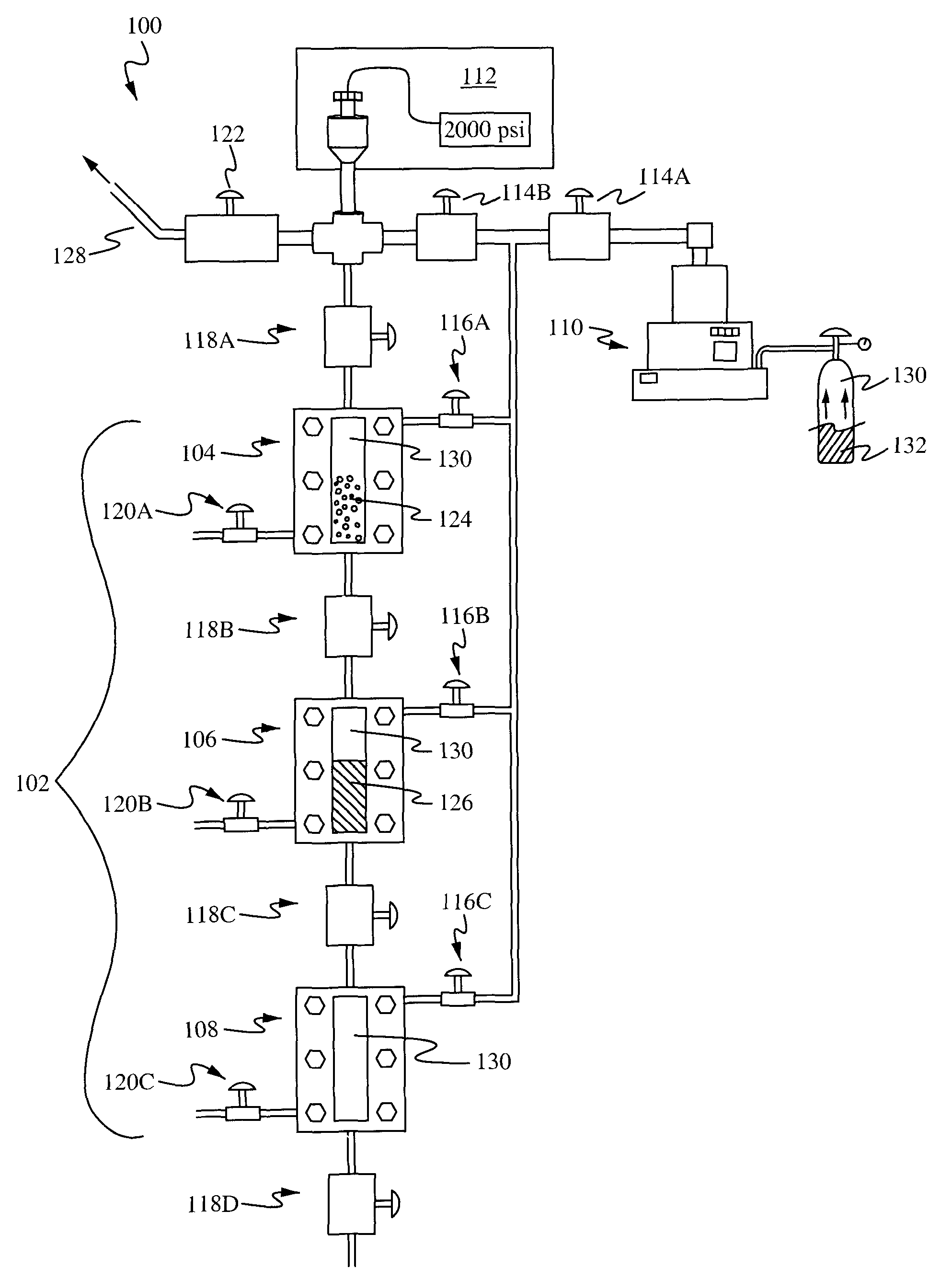
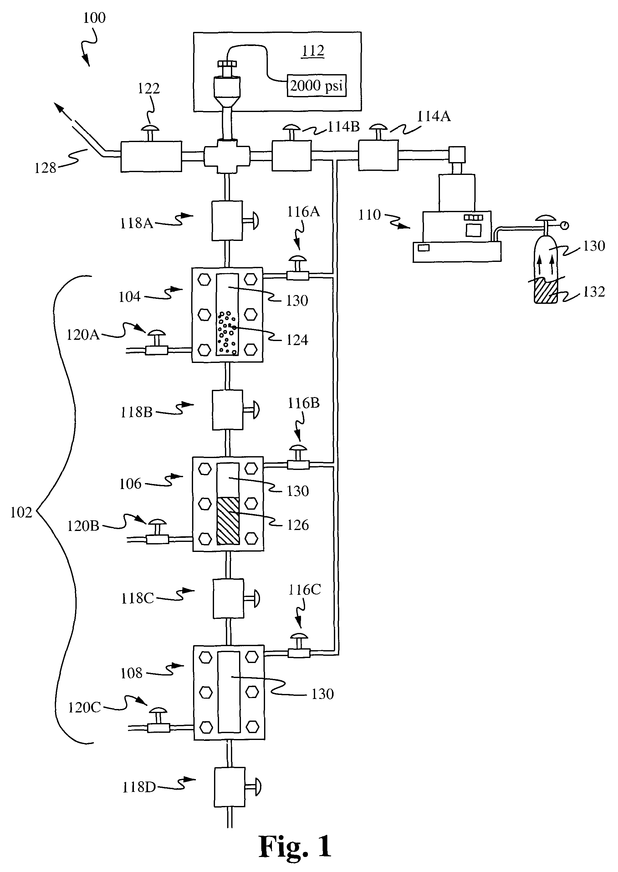
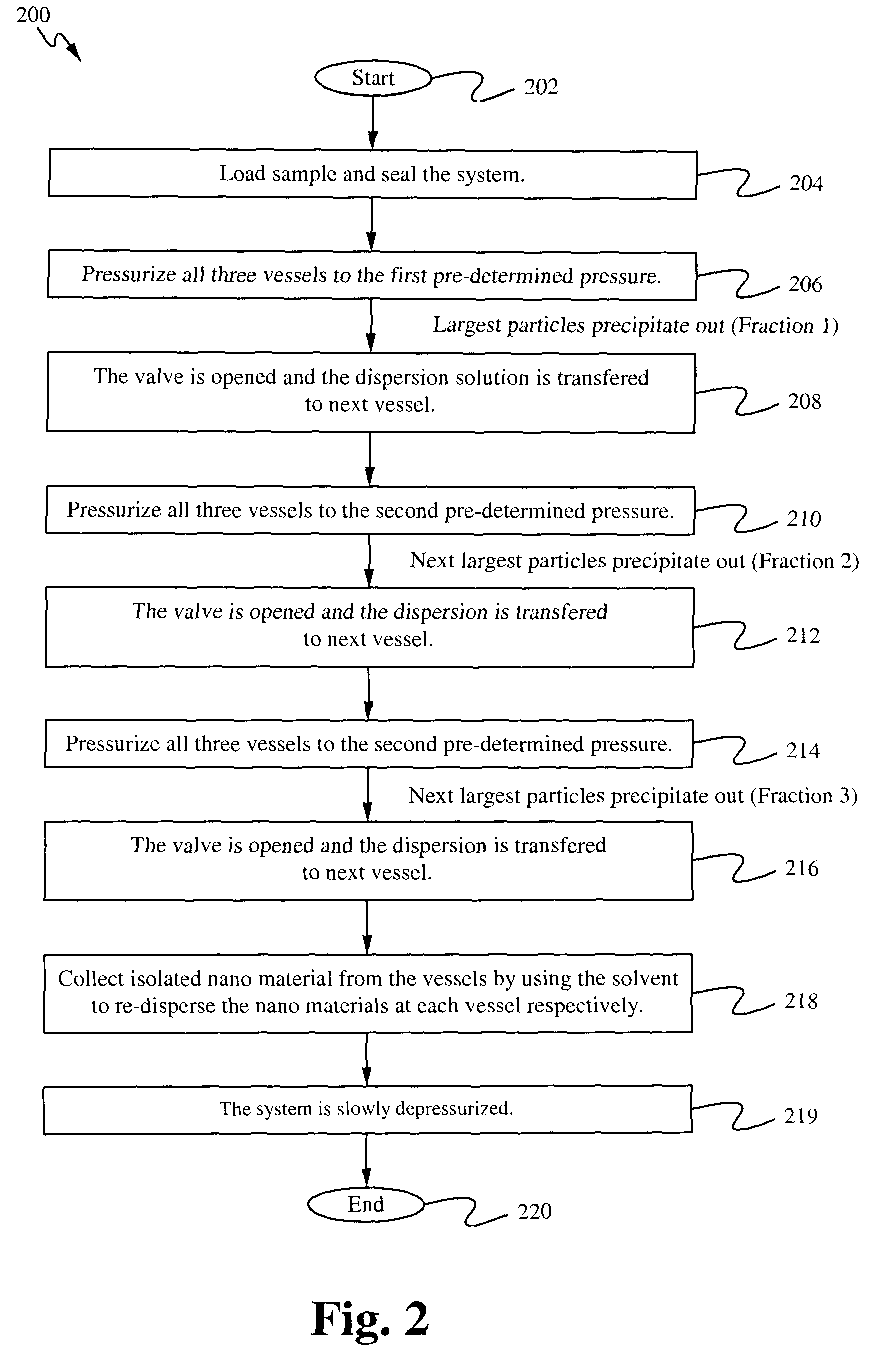
[0028]Methods and apparatuses for precise, rapid and improved separation of nanoparticles by size relies on a solvent / antisolvent method that uses a gaseous antisolvent to create a tunable gas expanded liquid are provided. The antisolvent is carbon dioxide (CO2) in some embodiments. Pressurized gaseous antisolvent is placed over a nanoparticle solution. By changing the pressure of the antisolvent, the resulting fraction of antisolvent in the solution is able to be increased or decreased. Given that particle dispersibility is a function of antisolvent in the liquid, particles of any given target sizes are able to be made to precipitate by simple manipulation of the antisolvent pressure. Multiple monodisperse particle populations are able to be rapidly fractionated by adjusting only the antisolvent pressure and the liquid location, thereby eliminating the difficulties associated with traditional methods that are time and solvent intensive, expensive, and / or have limited throughput.

[00...


PUM

PropertyMeasurementUnit
pressureaaaaaaaaaa
pressureaaaaaaaaaa
volumeaaaaaaaaaa

Abstract

The present application provides apparatuses and methods for the size-selective fractionation of ligand-capped nanoparticles that utilizes the tunable thermophysical properties of gas-expanded liquids. The nanoparticle size separation processes are based on the controlled reduction of the solvent strength of an organic phase nanoparticle dispersion through increases in concentration of the antisolvent gas, such as CO2, via pressurization. The method of nanomaterial separation contains preparing a vessel having a solvent and dispersed nanoparticles, pressurizing the chamber with a gaseous antisolvent, and causing a first amount of the nanoparticles to precipitate, transporting the solution to a second vessel, pressurizing the second vessel with the gaseous antisolvent and causing further nanoparticles to separate from the solution.

Description

U.S. GOVERNMENT AGENCY AND THE GOVERNMENT CONTRACT[0001]The invention was made by an agency of the United States Government or under a contract with an agency of the United States Government. The name of the U.S. Government agency and the Government contract number are: DOE-National Energy Technology Laboratory Grant No. DE-FG26-06NT42685.CROSS-REFERENCE TO RELATED APPLICATIONS[0002]This application claims priority from U.S. Provisional Patent Application Ser. No. 61 / 197,916, filed Oct. 31, 2008 and entitled “Method and Apparatus for Physical Separation of Different Sized Nanostructures”; which is hereby incorporated herein by reference in its entirety for all purposes. Further, U.S. Pat. No. 7,384,879 issued on Jun. 10, 2008 titled “SELECTION AND DEPOSITION OF NANOPARTICLES USING CO2-EXPANDED LIQUIDS,” U.S. patent application Ser. No. 12 / 082,189, filed on Apr. 8, 2008, titled “SELECTION OF NANOPARTICLES USING CO2-EXPANDED LIQUIDS,” and U.S. Provisional Patent Application Ser. No. 6...

Claims


Application Information

Patent Timeline
Patent Type & Authority Patents(United States)
IPC IPC(8): B07B4/00
CPCB82Y30/00B82Y40/00B01D21/0003B22F1/0545
Inventor ROBERTS, CHRISTOPHER B.SAUNDERS, STEVEN R.
Owner AUBURN UNIV
Why Eureka
Try Eureka