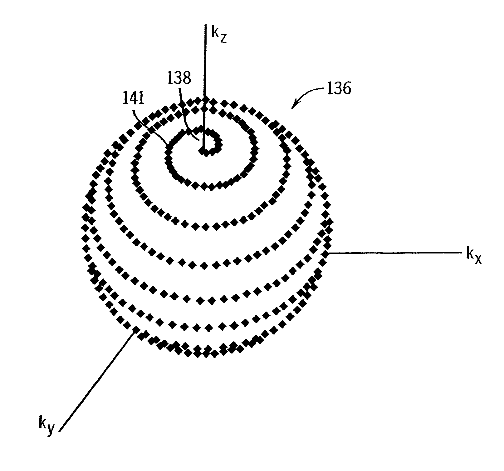
Accelerated shells trajectory MRI acquisition
a three-dimensional, trajectory technology, applied in the field of mri methods and systems, can solve the problems of two relatively large “polar icecaps” at the poles of the shells that are left unsampled, and about the same axis would not be able to cover, so as to shorten the tr and signal readout duration, reduce the contribution of fat signal and other off-resonance effects, and shorten the tr
- Summary
- Abstract
- Description
- Claims
- Application Information
AI Technical Summary
Benefits of technology
Problems solved by technology
Method used
Image

Examples
Embodiment Construction
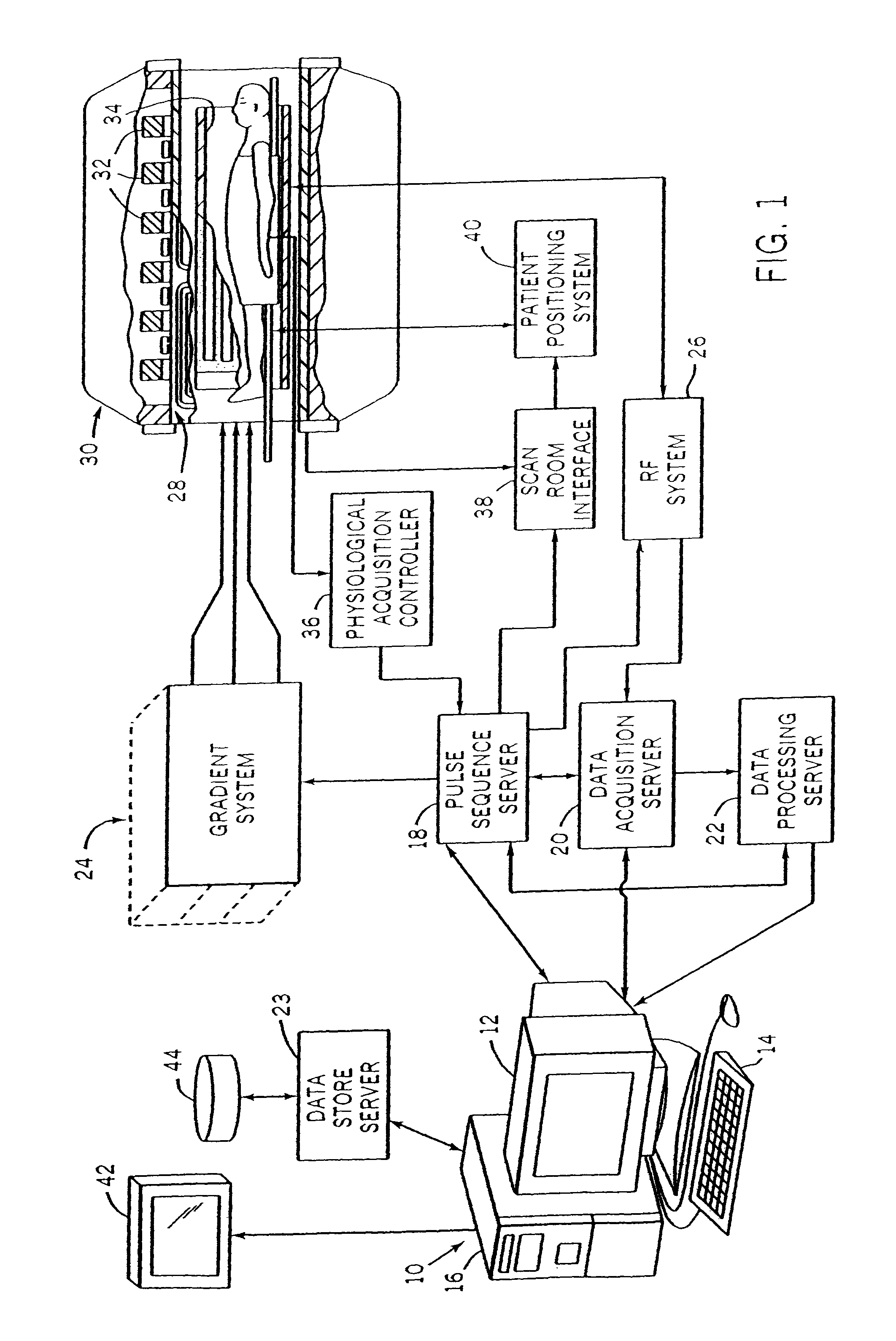
[0033]Referring particularly to FIG. 1, the preferred embodiment of the invention is employed in an MRI system. The MRI system includes a workstation 10 having a display 12 and a keyboard 14. The workstation 10 includes a processor 16 which is a commercially available programmable machine running a commercially available operating system. The workstation 10 provides the operator interface which enables scan prescriptions to be entered into the MRI system.
[0034]The workstation 10 is coupled to four servers: a pulse sequence server 18; a data acquisition server 20; a data processing server 22, and a data store server 23. In the preferred embodiment the data store server 23 is performed by the workstation processor 16 and associated disc drive interface circuitry. The remaining three servers 18, 20 and 22 are performed by separate processors mounted in a single enclosure and interconnected using a 64-bit backplane bus. The pulse sequence server 18 employs a commercially available micro...
PUM
 Abstract
Description
Claims
Application Information
 - R&D
- Intellectual Property
- Life Sciences
- Materials
- Tech Scout
- Unparalleled Data Quality
- Higher Quality Content
- 60% Fewer Hallucinations
Browse by: Latest US Patents, China's latest patents, Technical Efficacy Thesaurus, Application Domain, Technology Topic, Popular Technical Reports.
© 2025 PatSnap. All rights reserved.Legal|Privacy policy|Modern Slavery Act Transparency Statement|Sitemap|About US| Contact US: help@patsnap.com