
Electrical terminal for terminating a wire

a technology of electric terminals and terminals, which is applied in the direction of coupling bases/cases, coupling devices, and connections effected by permanent deformation, etc., can solve the problems of aluminum as a conductor material being an oxide layer that may build on the exterior surface of the conductor, and the electrical conductivity of the oxide layer is relatively poor

Active Publication Date: 2012-07-03
TYCO ELECTRONICS LOGISTICS AG (CH) +1
View PDF14 Cites 26 Cited by
  • Summary
  • Abstract
  • Description
  • Claims
  • Application Information

AI Technical Summary

Benefits of technology

The patent text describes an electrical terminal that can be used to terminate a wire. The terminal includes a contact and a crimp barrel that is designed to be crimped around the end of the wire. The crimp barrel has a base and side walls that form an opening to receive the wire. The side walls are folded over when crimped over the wire, creating a gap between the base and the side walls. The terminal also includes an embossment that extends from the base or the side walls. This embossment helps to secure the wire in place within the crimp barrel. The technical effect of this design is to provide a reliable and secure connection between the wire and the electrical terminal, even in situations where the wire is not perfectly aligned or surrounded by insulation.

Problems solved by technology

However, aluminum is not without disadvantages.
For example, one disadvantage of using aluminum as a conductor material is an oxide layer that may build on the exterior surface of the conductor.
Such an oxide layer has relatively poor electrical conductivity.
Another disadvantage of aluminum is electrochemical corrosion.
Exposure of a conductor to moisture may cause the conductor to corrode.
For example, moisture that infiltrates a crimp interface between a conductor and a crimp barrel may cause the conductor to experience electrochemical corrosion, and thereby begin to dissolve.
Such exposed ends of conductors may experience corrosion from exposure to moisture within the operating environment of the electrical terminal.
Corrosion is thus an issue when using aluminum as a conductor material.
Corrosion may therefore be especially problematic when terminating aluminum conductors to copper-based electrical terminals.
However, because aluminum has a reduced amount of electrical conductivity relative to copper, aluminum conductors need to have a larger cross-sectional area than copper conductors for a given electrical current carrying capacity.
A larger crimp barrel and silicone gasket would therefore need to be manufactured to accommodate the larger aluminum conductor, which may increase the cost of an assembly of the electrical terminal and wire.
However, such techniques are not without disadvantages.
For example, nickel plating may require the use of galvanic plating, which may be relatively expensive.
Additionally, the relatively hard nickel surface layer may be harmful to the tool used to crimp the crimp barrel around the wire.
Moreover, there is a probability that the nickel surface layer will crack during crimping, which would create possible corrosion paths.
Aluminum plating is not currently possible with usual plating process and may therefore require the implementation of new plating technology, such as physical vapor deposition (PVD), which may be expensive.
Moreover, even with new plating technology such as PVD there will still be exposed edges of the plating layer, which will transfer the corrosion issue to a different place on the electrical terminal.
Fabricating the base material of the crimp barrel out of aluminum material may also be disadvantageous.
However, aluminum has relatively poor spring characteristic properties, so there is no possibility to form a spring beam out of aluminum.
Accordingly, fabricating the crimp barrel out of aluminum material would be restricted to use on electrical terminals that do not include a spring beam or it would be necessary to use different materials as the base materials of the crimp barrel and the electrical contacts, which may be expensive, time-consuming, and / or difficult to manufacture.

Method used


Image

  • Electrical terminal for terminating a wire
  • Electrical terminal for terminating a wire
  • Electrical terminal for terminating a wire

Examples


Embodiment Construction

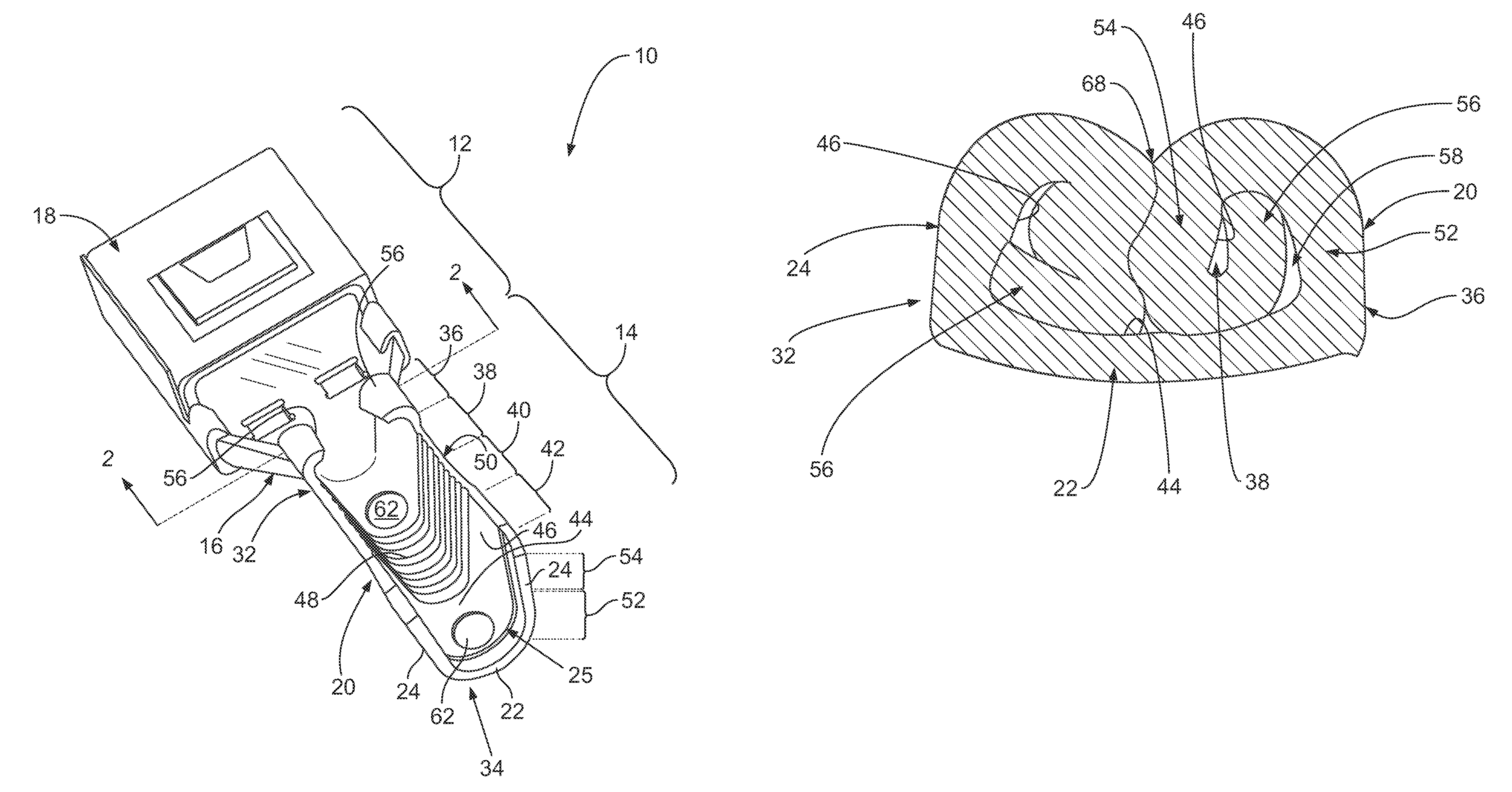
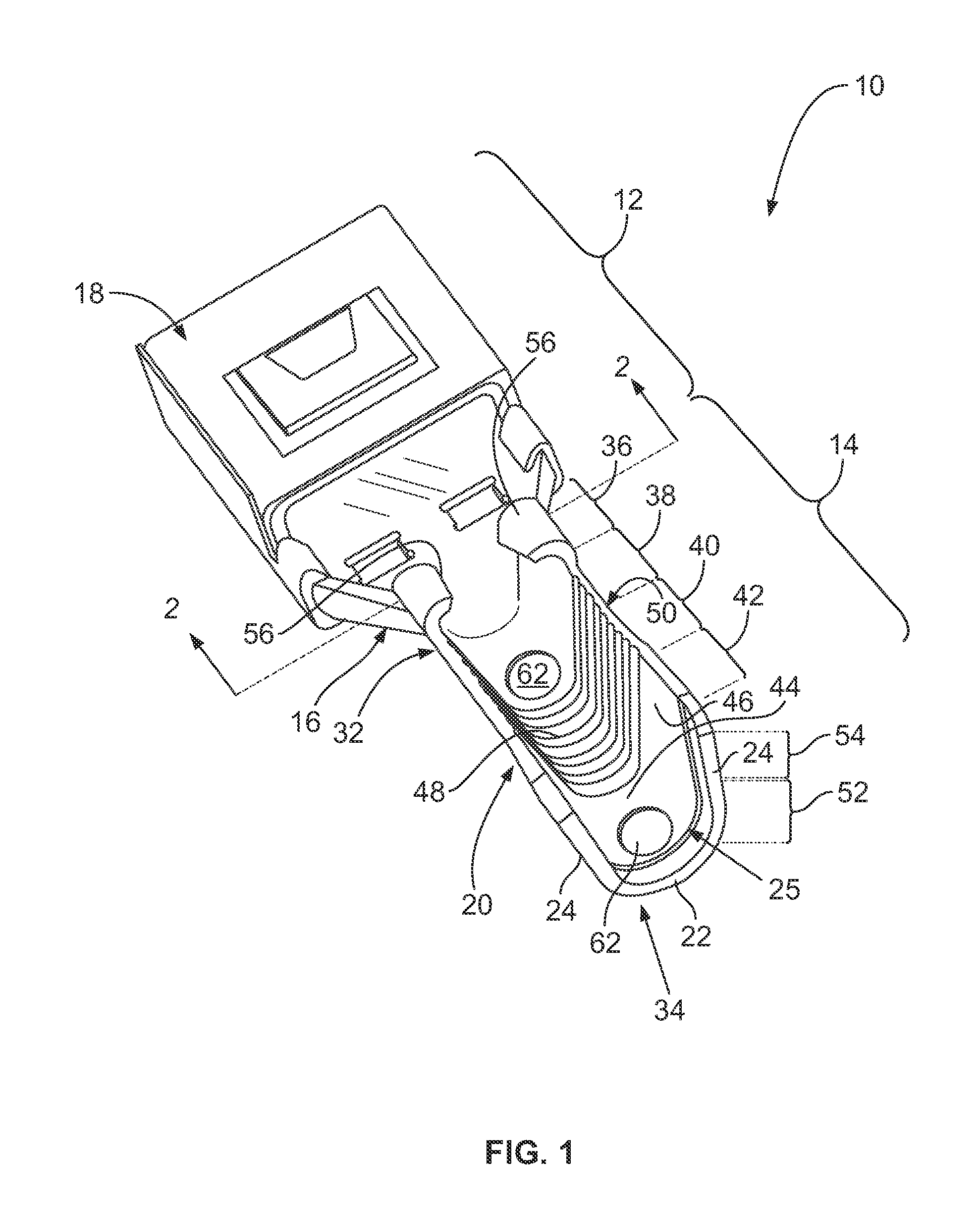
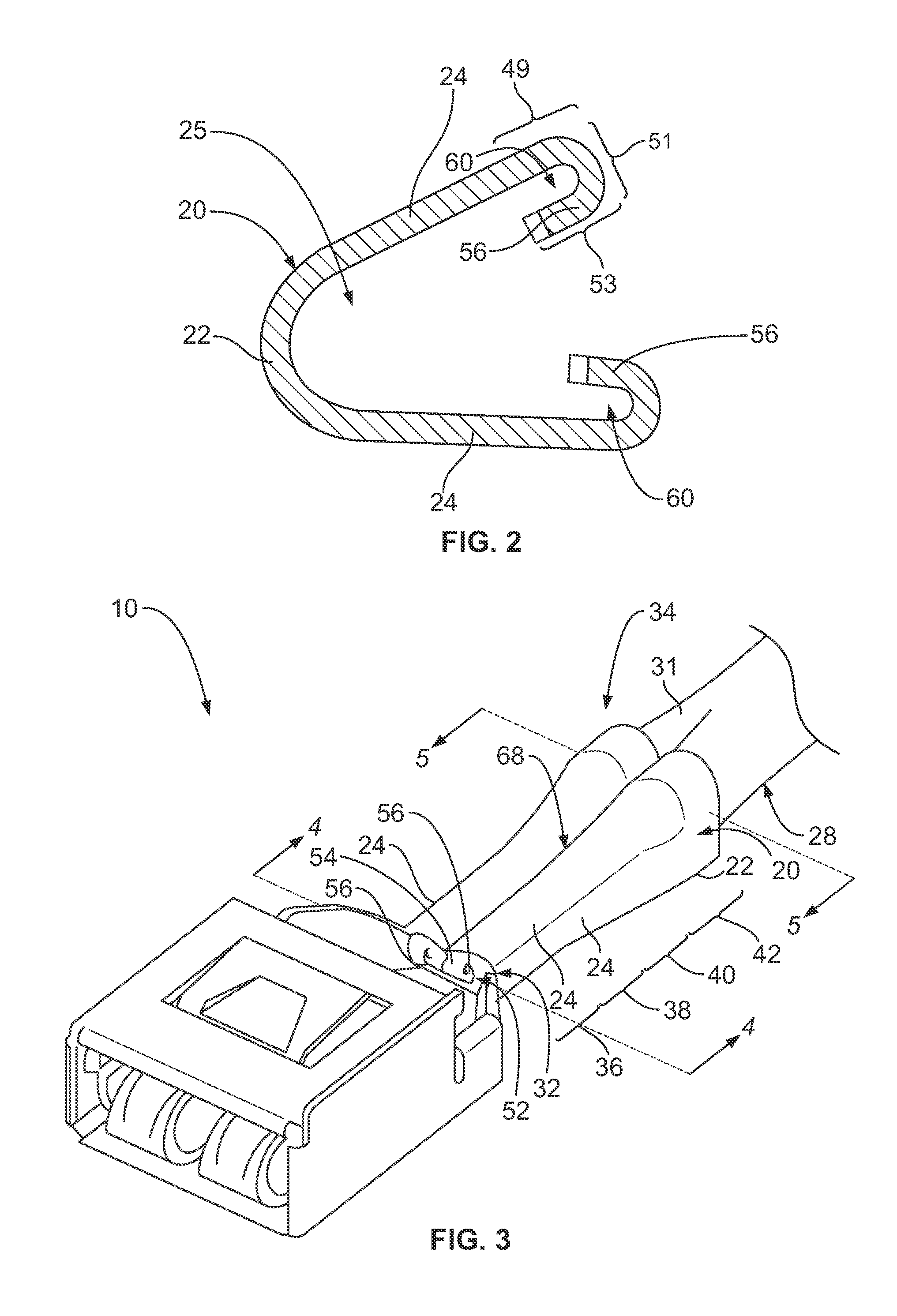
[0022]FIG. 1 is a perspective view of an exemplary embodiment of an electrical terminal 10. The terminal 10 includes an electrical contact segment 12 and a crimp segment 14 that extends from an end 16 of the electrical contact segment 12. The electrical contact segment 12 includes an electrical contact 18. In the exemplary embodiment, the electrical contact 18 is a receptacle that is configured to receive a mating contact (not shown) therein. But, the electrical contact 18 shown herein is meant as exemplary only. The electrical terminal 10 is not limited to the electrical contact 18 shown herein, but rather the electrical terminal 10 may include any type of electrical contact 18, such as, but not limited to, a crimp barrel, a spring contact, a beam contact, a tab, a structure having an opening for receiving a threaded or other type of mechanical fastener, and / or the like.

[0023]The crimp segment 14 includes a crimp barrel 20. The crimp banel 20 includes a base 22 and opposing side wa...


PUM


Abstract

An electrical terminal is provided for terminating a wire. The electrical terminal includes an electrical contact and a crimp barrel extending from the electrical contact. The crimp barrel is configured to be crimped around an end of the wire. The crimp barrel includes a base and opposing side walls that extend from the base. The base and the side walls define an opening of the crimp barrel that is configured to receive the end of the wire therein. The side walls extend outwardly from the base to ends. The side walls include base segments that extend from the base and end segments that extend from the base segments and include the ends. A sealing wing extends from the end of at least one of the side walls. The side walls are configured to be folded over when crimped over the end of the wire such that a gap is defined between the end segment and the base segment of at least one of the side walls. The sealing wing is configured to extend within the gap between the end segment and the base segment of the corresponding side wall when the side walls are crimped over the end of the wire.

Description

CROSS REFERENCE TO RELATED APPLICATIONS[0001]This application is a nonprovisional patent application of, and claims priority to and the benefit of, the filing date of U.S. Provisional Patent Application No. 61 / 394,260, filed on Oct. 18, 2010 and entitled “Electrical Terminal for Terminating a Wire”, which is hereby incorporated by reference in its entirety.BACKGROUND OF THE INVENTION[0002]The subject matter described and / or illustrated herein relates generally to electrical terminals that terminate wires.[0003]Electrical terminals are often used to terminate the ends of wires. Such electrical terminals typically include an electrical contact and a crimp barrel. The crimp barrel includes an opening that receives an end of the wire therein. The crimp barrel is crimped around the end of the wire to establish an electrical connection between the one or more conductors of the wire and the terminal as well as to mechanically hold the electrical terminal on the wire end. When crimped over ...

Claims


Application Information

Patent Timeline
Patent Type & Authority Patents(United States)
IPC IPC(8): H01R4/10
CPCH01R4/185H01R13/5221H01R13/5216H01R43/005H01R4/18H01R13/52
Inventor CORMAN, NEDBLUMMEL, UWESCHMIDT, HELGECOPPER, CHARLES D.BOYER, RAYMOND DENNISWEAVER, DAVID B.HALL, JOHN WESLEYMYER, JOHN M.
Owner TYCO ELECTRONICS LOGISTICS AG (CH)
Learn More