Organic electroluminescence module having a bent strip conductor

a technology of electroluminescence module and bent strip, which is applied in the direction of discharge tube/lamp details, discharge tube luminescnet screen, organic semiconductor device, etc., can solve the problems of wiring board processing loss and high manufacturing cost, and achieve the effect of reducing processing loss, lowering manufacturing cost and facilitating the absorption of deviations in siz

Inactive Publication Date: 2012-06-26
PANASONIC CORP
View PDF1 Cites 6 Cited by
  • Summary
  • Abstract
  • Description
  • Claims
  • Application Information

AI Technical Summary

Benefits of technology

[0011]According to the present invention, the wiring boards are formed by the bent strip conductor, such that the wiring boards having a width satisfying a shape of the electrodes without cutting a conductive plate into a U shape, and the processing loss is reduced, thereby lowering the manufacturing cost.
[0012]According to the present invention, the wiring boards contact the electrodes through a plurality of contacting portions, such that the wiring boards surely contact the electrodes even if the electrodes have high resistance, so as to uniformly supply the power to the electrodes, thereby obtaining a uniform light emitting surface.
[0013]According to the present invention, the wiring board is a flexible wiring substrate, and is bent to press and contact the electrodes, such that when the flexible wiring substrate is used to press and contact a plurality of electrodes, it is easier to absorb the size deviation of the flexible substrate, contact position deviation, and electrode position deviation.

Problems solved by technology

Therefore, the part of the base material surrounded by the U shape having the corners becomes useless, a processing loss of the wiring boards 105P and 104M is relatively high, and a manufacturing cost becomes high.

Method used


Image

  • Organic electroluminescence module having a bent strip conductor
  • Organic electroluminescence module having a bent strip conductor
  • Organic electroluminescence module having a bent strip conductor

Examples


first embodiment

Variation of First Embodiment

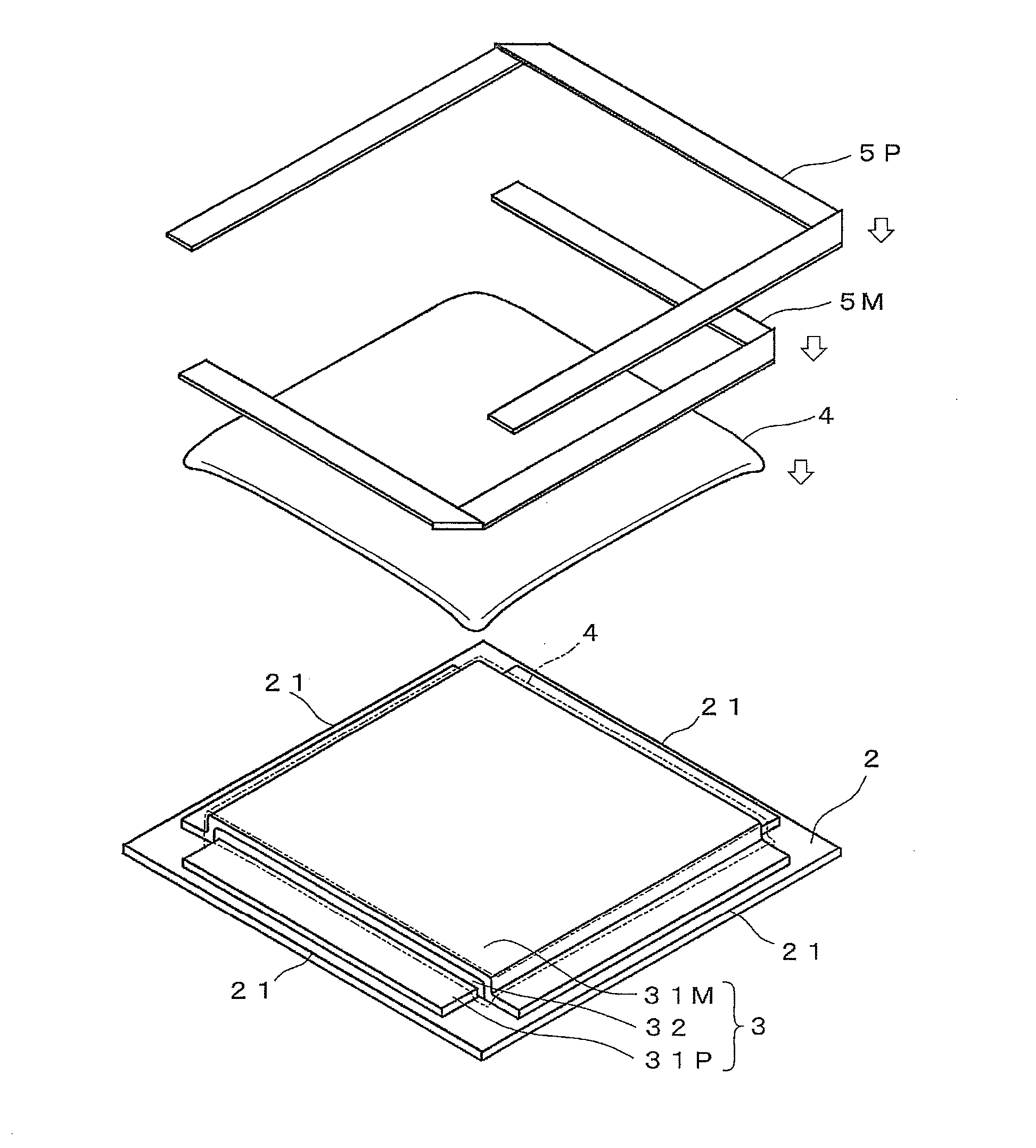
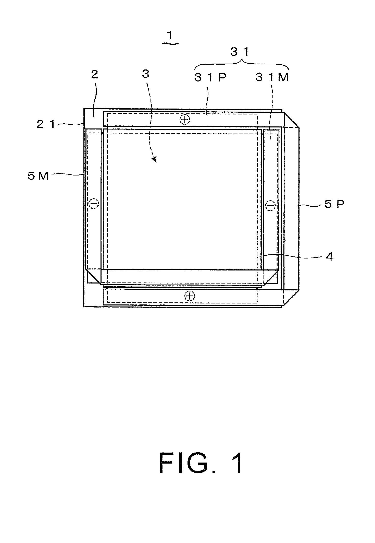
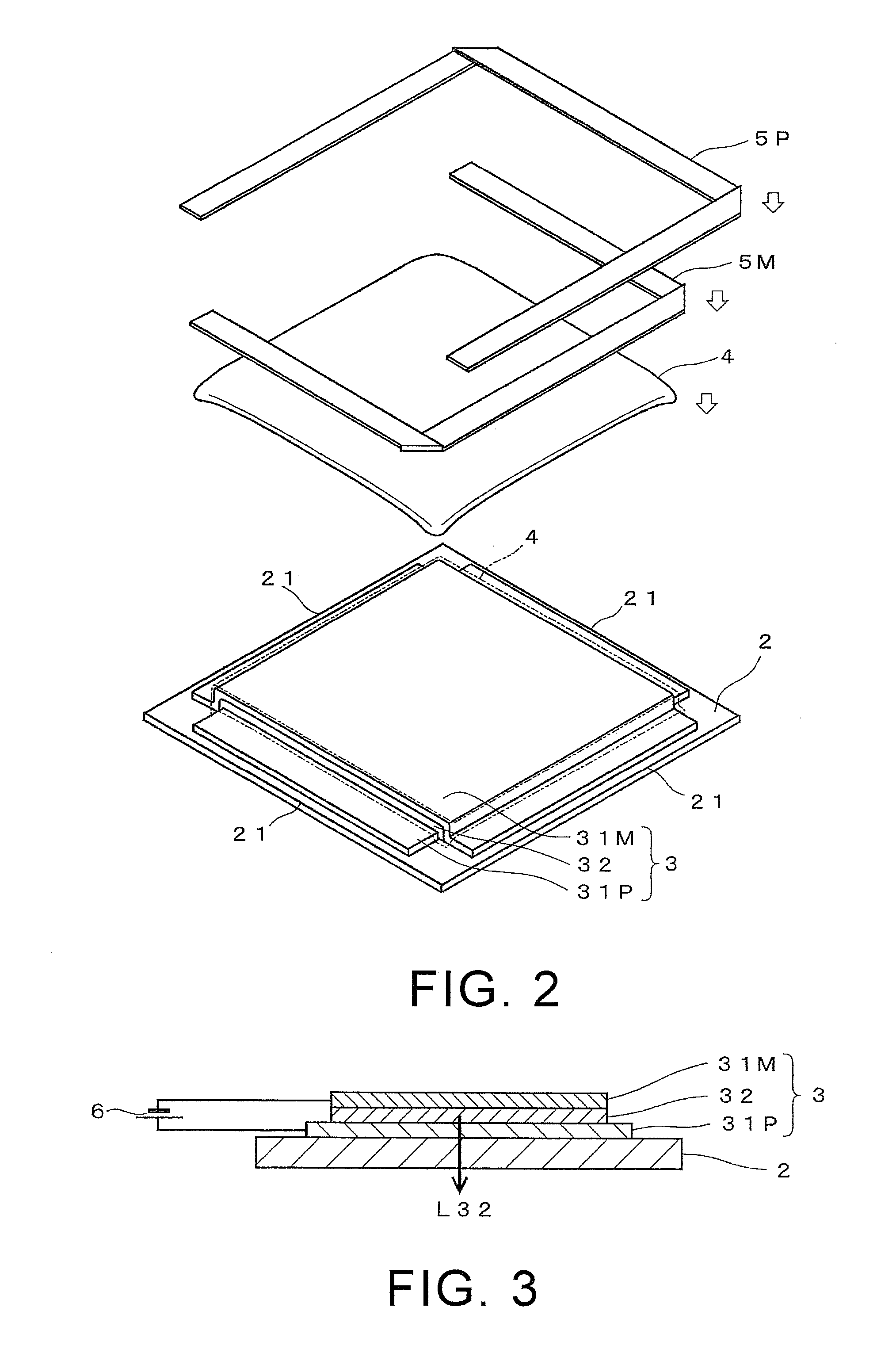
[0037]Next, referring to FIGS. 7 to 9, an organic EL module according to the variation of the first embodiment is described. As shown in FIGS. 7 and 8, the organic EL module 11 of this variation is accommodated in a case 7. In this variation, wiring boards 5 are lead frames, and parts of the wiring boards 5 contacting electrodes 31 are in a wave shape. The wiring boards 5 include a wiring board 5P of a positive side and a wiring board 5M of a negative side disposed in pair, and parts of the wiring board 5P and the wiring board 5M contacting the anode 31P and the cathode 31M respectively form the wave shape. Alternatively, only the wiring board 5P of the positive side in the wiring boards 5 is in the wave shape, and the wiring board 5M of the negative side is in a flat shape.

[0038]The case 7 is made by resin processed into a case shape, and is formed by a front case 71 and a back case 72. In the case 7, an element substrate 2 emitting the light serves as ...

second embodiment

[0041]Referring to FIG. 10, an organic EL module according to a second embodiment of the present invention is described. In the organic EL module 12 of this embodiment, the wiring board 5 is a flexible wiring substrate having flat conductors on two sides of a flexible substrate, so as to replace the single-plate conductor of the first embodiment. The flexible wiring substrate includes an insulating substrate serving as a base plate; conductors on two sides of the substrate, and cover layers (surface protective films) on surfaces of the conductors. The wiring board 5 is formed by bending the flexible wiring substrate in a strip shape in a manner that parts of the strip on the same surface contacting each other, so as to form a frame shape of surrounding the organic EL element 3. Parts of the conductors of the wiring board 5 contacting electrodes 31 are exposed from the cover layers, such that the conductor on one side is connected to an anode 31P, and then the flexible wiring substra...


PUM


Abstract

An organic electroluminescence (EL) module capable of reducing a processing loss of wiring boards for supplying power to an anode and a cathode is provided. Each wiring board (5) is formed by bending a strip conductor in a manner that parts of the strip in the same surface contacting each other, and is arranged on the outer periphery of the element substrate (2) in a manner of connecting the extended anode (31P) with the same pole and connecting the extended cathode (31M) with the same pole. In this manner, the wiring boards (5) having a width satisfying a shape of the electrodes without cutting a conductive plate into a U shape.

Description

CROSS-REFERENCE TO RELATED APPLICATION[0001]This application claims the priority benefit of Japan application serial no. 2009-038008, filed Feb. 20, 2009. The entirety of the above-mentioned patent application is hereby incorporated by reference herein and made a part of specification.BACKGROUND OF THE INVENTION[0002]1. Field of the Invention[0003]The present invention generally relates to an organic electroluminescence (EL) module, capable of emitting light through organic EL.[0004]2. Description of Related Art[0005]Conventionally, an organic EL module (for example, referring to Japanese Laid-Open Patent Publication No. 2007-299740), which is capable of obtaining a surface light source by enabling an organic substance to emit light, is known. FIG. 11 shows the organic EL module. The organic EL module 100 includes a quadrangular element substrate 102 formed by glass, an organic EL element 103 formed by laminating anodes 131P, an organic layer, and cathodes 131M in sequence, a sealin...

Claims


Application Information

Patent Timeline
Patent Type & Authority Patents(United States)
IPC IPC(8): H01J1/62H01J63/04
CPCH01L51/5203H01L2251/5361H05K1/028H05K1/147H05K1/189H05K2201/055H05K2201/10128H10K50/805
Inventor KAWACHI, HIDEHARUKONISHI, HIROFUMITANAHASHI, OSAMUFUKANO, SATOSHIOKAWA, MASANAO
Owner PANASONIC CORP
Why Eureka
Try Eureka