
Messenger supported overhead cable for electrical transmission

a technology of overhead cable and measuring device, applied in the direction of overhead installation, electric cable suspension arrangement, electric cable installation, etc., can solve the problems of inseparable coupling of mechanical strength member, inability to pivot, and inability to withstand high temperature and other problems, to achieve the effect of convenient pivoting coupling

Active Publication Date: 2012-06-19
ADVANCED TECH HLDG
View PDF54 Cites 10 Cited by
  • Summary
  • Abstract
  • Description
  • Claims
  • Application Information

AI Technical Summary

Benefits of technology

[0017]In another preferred embodiment, the conductor and the messenger member are spaced apart from each other a predetermined distance. The coupling means facilitates the maintenance of the separation of the messenger relative to the conductor.
[0021]In another preferred embodiment, at least one of the messenger indentation and the conductor indentation includes a liner or a resilient member to preclude damage to the respective one of the conductor and messenger relative to the bracket member.
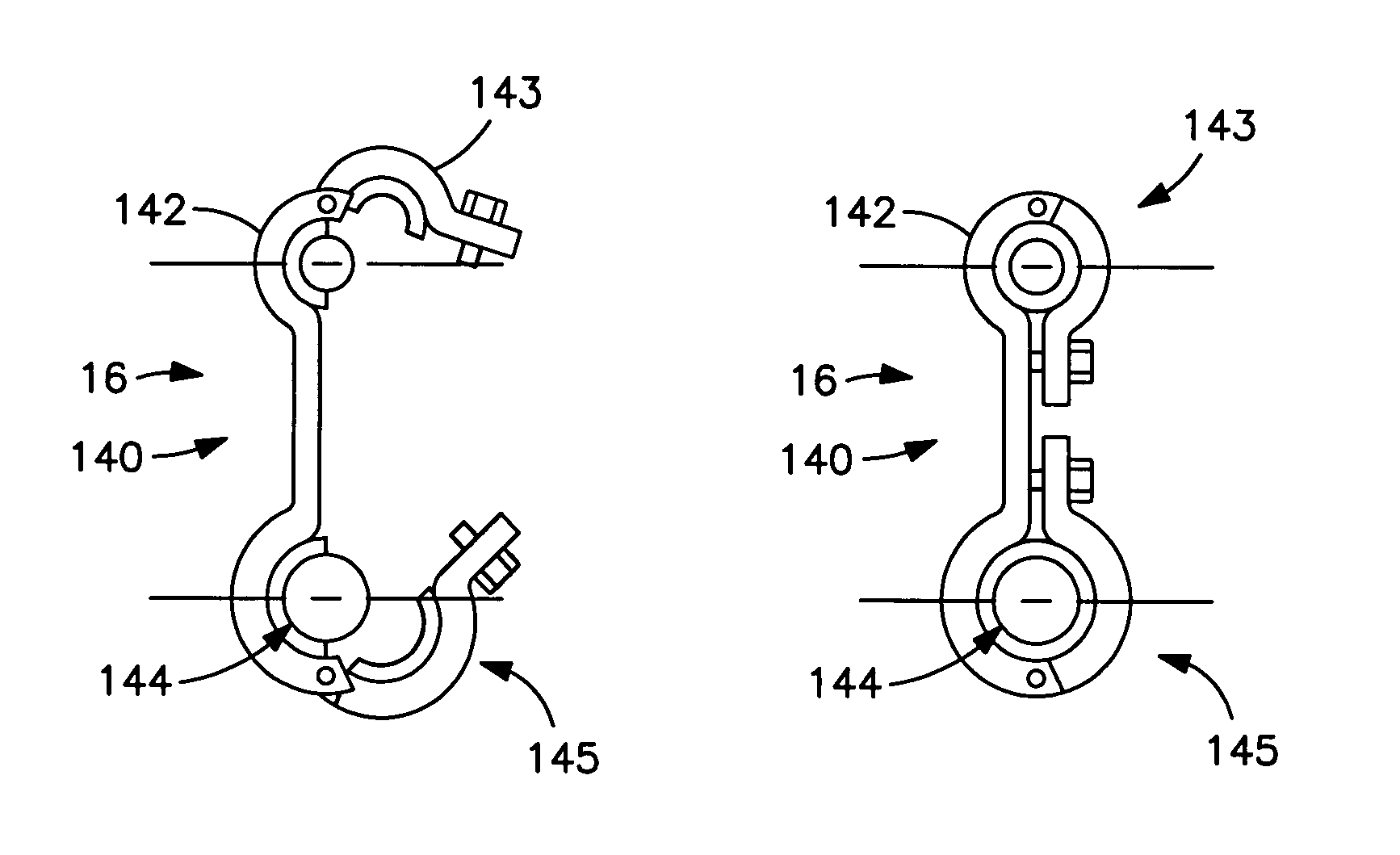
[0022]In another preferred embodiment, the coupling means comprises a messenger tray assembly defining a channel structurally configured to receive the messenger, a conductor tray assembly defining a channel structurally configured to receive the conductor, and a pivotable coupling assembly which facilitates the pivotable coupling of the messenger tray assembly relative to the conductor tray assembly.
[0026]In a preferred embodiment, the apparatus further comprises a second conductor. The first conductor, the second conductor and the messenger member are spaced apart from each other a predetermined distance. The coupling means facilitates the maintenance of the separation of the messenger relative to the conductor. The coupling member comprises a frame member having a central region and opposing wing members. The messenger member is coupled to the central region of the frame member, and each conductor is pivotably connected to opposing wing members of the frame member.

Problems solved by technology

Amongst other drawbacks, such cables are susceptible to excessive sag in certain climates and under certain operating conditions.
Furthermore, such cables are susceptible to corrosion in other environments.
Despite these additional developments, the continuing drawback associated with the foregoing conductor solutions is that the mechanical strength member is intertwined and inseparably coupled with the current carrying conductor.
As such, the current carrying conductor is limited in construction due to the considerations of its mechanical strength.
Additionally, the mechanical strength member is limited by its compatibility with the conductor.
Such considerations often lead to a compromised solution.

Method used


Image

  • Messenger supported overhead cable for electrical transmission
  • Messenger supported overhead cable for electrical transmission
  • Messenger supported overhead cable for electrical transmission

Examples


Embodiment Construction

[0046]While this invention is susceptible of embodiment in many different forms, there is shown in the drawings and described herein in detail a specific embodiment with the understanding that the present disclosure is to be considered as an exemplification of the principles of the invention and is not intended to limit the invention to the embodiment illustrated.

[0047]It will be understood that like or analogous elements and / or components, referred to herein, may be identified throughout the drawings by like reference characters. In addition, it will be understood that the drawings are merely schematic representations of the invention, and some of the components may have been distorted from actual scale for purposes of pictorial clarity.

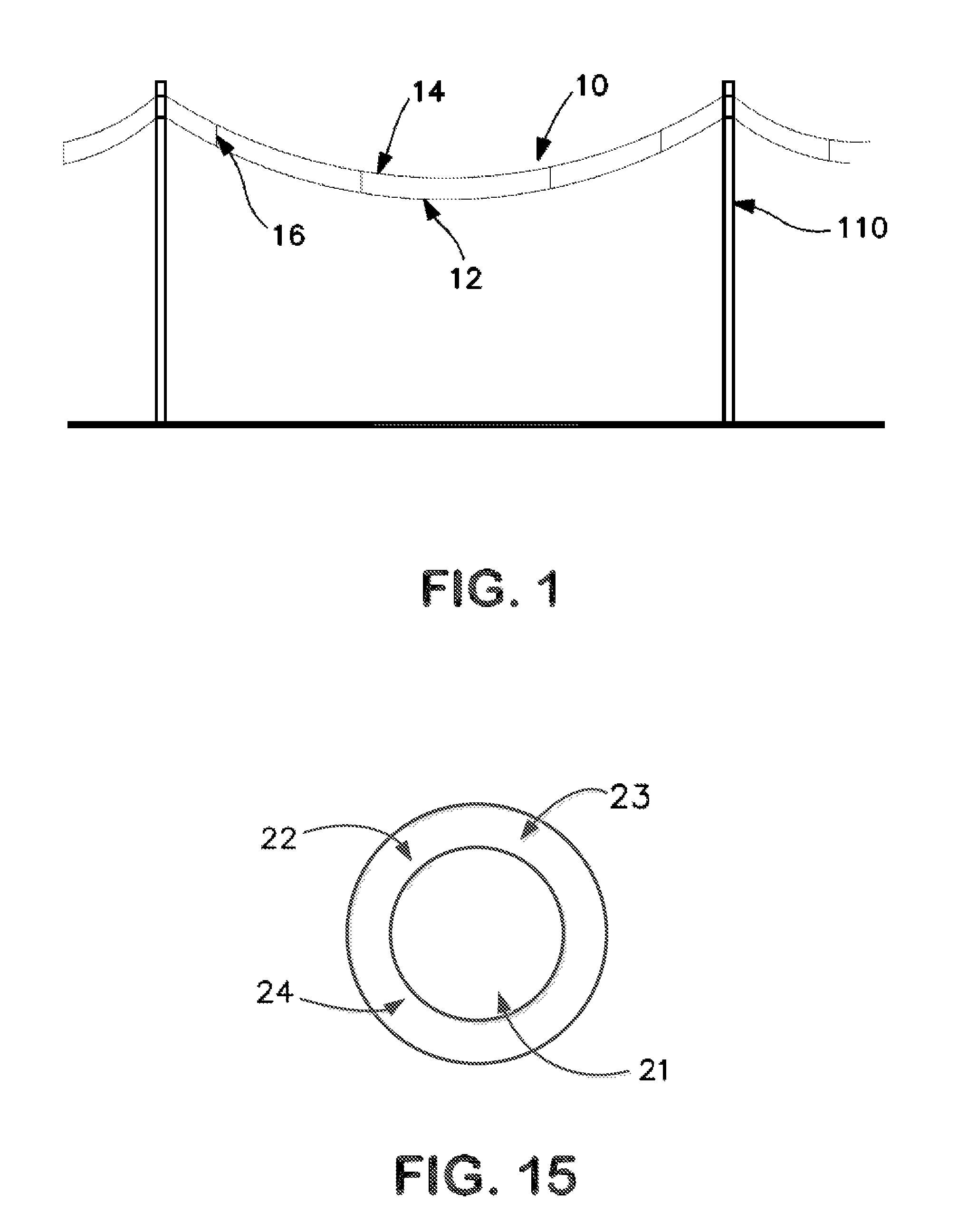
[0048]Referring now to the drawings and in particular to FIG. 1, the transmission line of the present invention is shown generally at 10. Typically, such conductors are used to transmit and distribute high voltage power forming the backbone of the n...


PUM


Abstract

A transmission line assembly for transmission and distribution of high voltage power which comprises a conductor, a separate messenger member and coupling means. The conductor has a predetermined length. The separate messenger member has a predetermined length. The coupling means couples the messenger to the conductor to the messenger. The messenger member and the conductor remain structurally separate from each other and functionally independent.

Description

CROSS-REFERENCE TO RELATED APPLICATION[0001]The present application claims priority from U.S. App. Ser. No. 60 / 854,289 filed Oct. 25, 2006, entitled “Messenger-supported Overhead Cables (MSC) for Electrical Transmission” the entire specification of which is hereby incorporated in its entirety.BACKGROUND OF THE INVENTION[0002]1. Field of the Invention[0003]The invention relates in general to a transmission cable intended for the transmission and distribution of electrical power, and typically, high voltage electrical power. More particularly, the transmission cable of the present invention separates the mechanical strength member from the electrical current carrying member, such that each can be designed and configured without dependence on the other.[0004]2. Background Art[0005]The demand for transmission and distribution cables increases with the greater demand for electricity. As the appetite for power increases, new electrical cables continue to be installed. Additionally, to inc...

Claims


Application Information

Patent Timeline
Patent Type & Authority Patents(United States)
IPC IPC(8): H02G7/08
CPCH02G7/08H02G7/12H01B9/008
Inventor GOCH, WAYMON P.
Owner ADVANCED TECH HLDG
Learn More