Creation of simulated disjoint rigid bodies in a finite element analysis

a technology of rigid bodies and finite elements, applied in the field of computer-aided engineering analysis, can solve the problems of inability to define a large number of rbs, requiring a tremendous amount of man hours (i.e., costs), and not being feasible in a production environmen

Active Publication Date: 2012-06-12
ANSYS
View PDF0 Cites 2 Cited by
  • Summary
  • Abstract
  • Description
  • Claims
  • Application Information

AI Technical Summary

Problems solved by technology

While this approach is straightforward for a relatively small number of rigid bodies, it is not feasible when a finite element analysis model contains a large number of rigid bodies (e.g., tens of thousands to millions).
It would require a tremendous amount of man hours (i.e., costs) to define the large number of RBs hence not feasible in a production environment.

Method used


Image

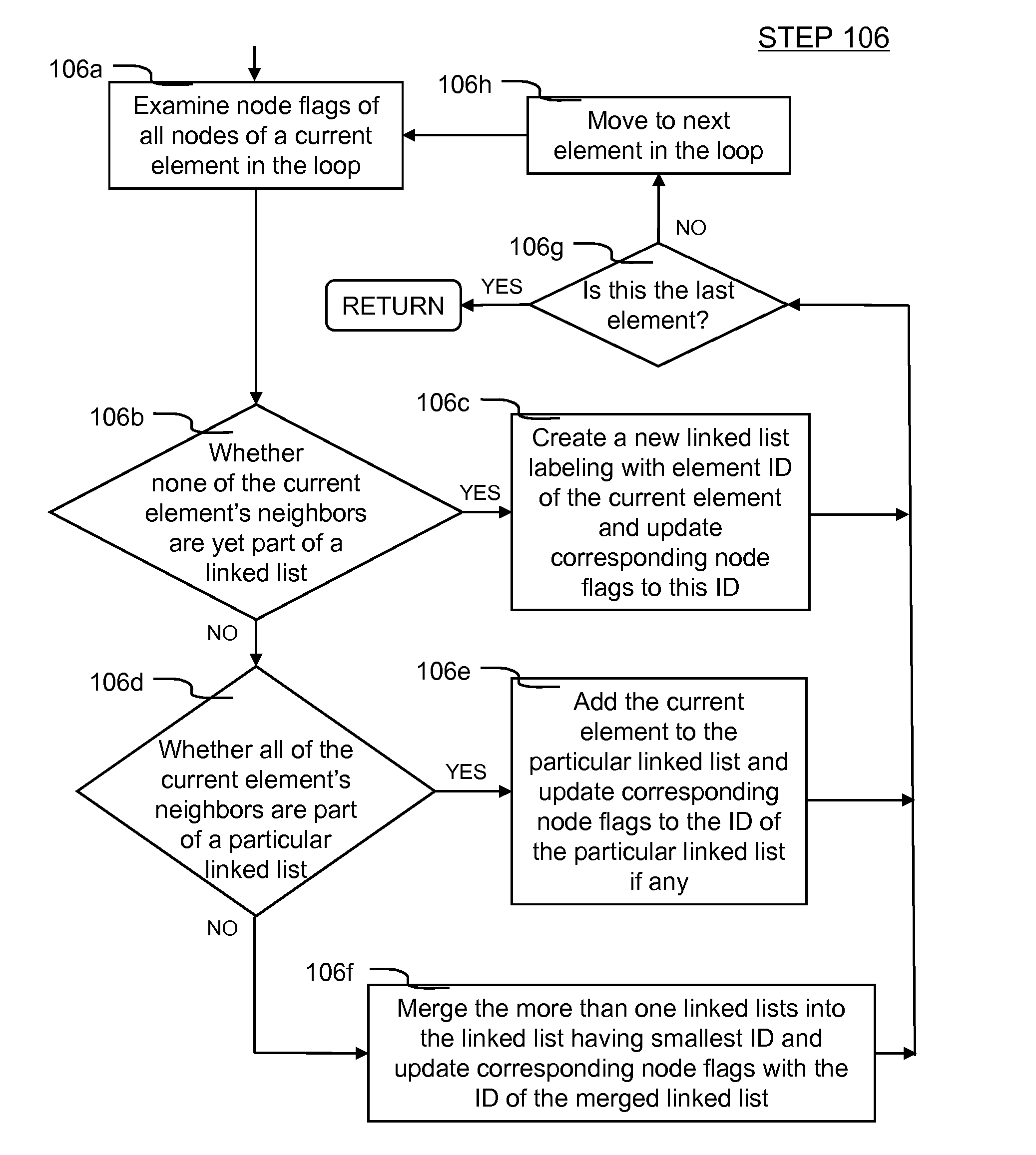
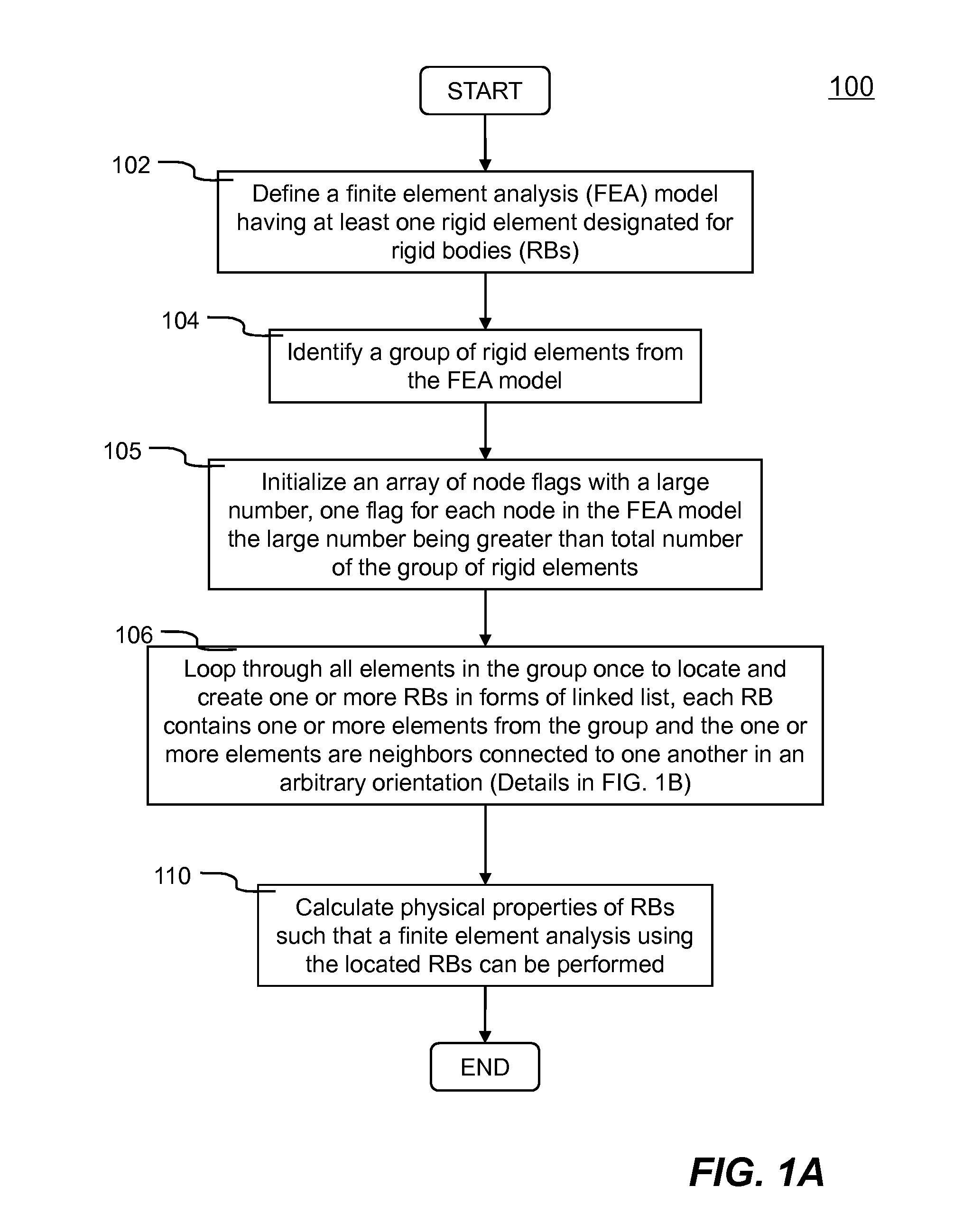
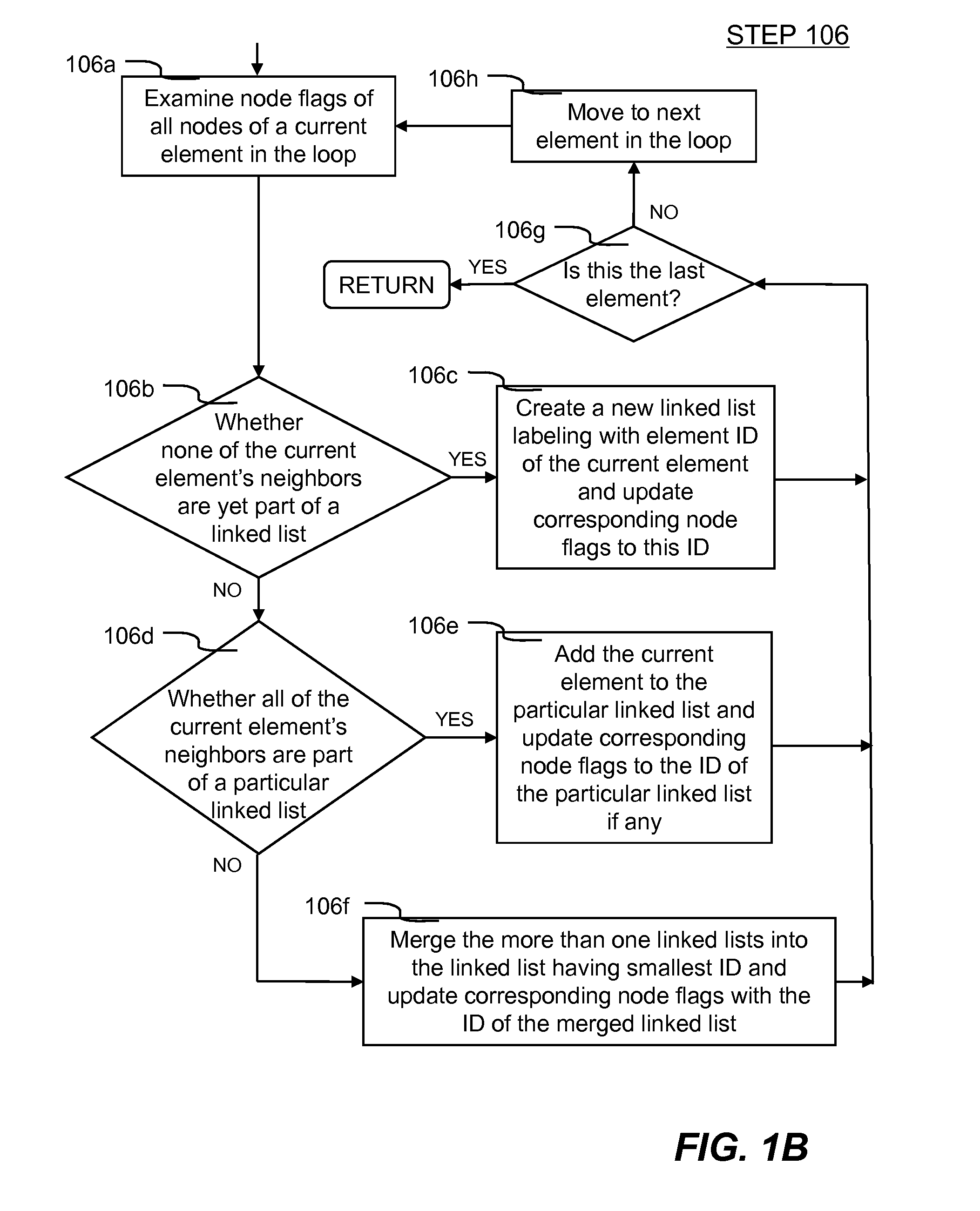
  • Creation of simulated disjoint rigid bodies in a finite element analysis
  • Creation of simulated disjoint rigid bodies in a finite element analysis
  • Creation of simulated disjoint rigid bodies in a finite element analysis

Examples


Embodiment Construction

[0020]In the following description, numerous specific details are set forth in order to provide a thorough understanding of the present invention. However, it will become obvious to those skilled in the art that the present invention may be practiced without these specific details. The descriptions and representations herein are the common means used by those experienced or skilled in the art to most effectively convey the substance of their work to others skilled in the art. In other instances, well-known methods, procedures, and components have not been described in detail to avoid unnecessarily obscuring aspects of the present invention.

[0021]Reference herein to “one embodiment” or “an embodiment” means that a particular feature, structure, or characteristic described in connection with the embodiment can be included in at least one embodiment of the invention. The appearances of the phrase “in one embodiment” in various places in the specification are not necessarily all referri...


PUM


Abstract

Improved methods and systems for defining and creating simulated rigid bodies in finite element analysis are disclosed. One or more rigid finite elements in a finite element model are designated for forming one or more simulated rigid bodies (RBs). Each simulated RB comprises an arbitrary number of rigid finite elements connecting to one another in an arbitrary shape. Each simulated RB is created by locating all of the elements embedded in the model through shared node or nodes. A procedure of using element definition as a guide to set up an array of node flags, each node flag for one node such that all RBs defined in the model can be located efficiently. Once all RBs have been located, each unique RB is defined as a unique list of connected rigid finite elements.

Description

CROSS REFERENCE TO RELATED APPLICATIONS[0001]This application claims priority from a U.S. Provisional Patent Application Ser. No. 61 / 253,161 for “CREATION OF SIMULATED DISJOINT RIGID BODIES IN A FINITE ELEMENT ANALYSIS”, filed Oct. 20, 2009, the entire contents of which are incorporated herein by reference.FIELD OF THE INVENTION[0002]The present invention generally relates to computer aided engineering analysis, more particularly to systems and methods of creating simulated rigid bodies (RBs) in a finite element analysis without explicitly defining any identifier for RBs.BACKGROUND OF THE INVENTION[0003]Computer aided engineering (CAE) has been used for supporting engineers in many tasks. For example, in a structure or engineering product design procedure, CAE analysis, particularly finite element analysis (FEA), has often been employed to evaluate simulated responses (e.g., stresses, displacements, etc.) under various simulated loading conditions (e.g., static or dynamic).[0004]FEA...

Claims


Application Information

Patent Timeline
Patent Type & Authority Patents(United States)
IPC IPC(8): G06F17/50
CPCG06F17/5018G06F30/23
Inventor HALLQUIST, JOHN O.WAINSCOTT, BRIAN
Owner ANSYS
Why Eureka
Try Eureka