
Retractable zoom lens having a variable aperture-stop mechanism

a variable aperture and lens technology, applied in the direction of shutters, mountings, instruments, etc., can solve the problems of complicated mechanical structure and electrical control system of the cost of adopting such a multi-function diaphragm control mechanism, so as to increase/reduce the operation, complicate the structure of the variable aperture-stop mechanism, and increase the size of the variable aperture-stop

Inactive Publication Date: 2012-06-12
HOYA CORP
View PDF6 Cites 1 Cited by
  • Summary
  • Abstract
  • Description
  • Claims
  • Application Information

AI Technical Summary

Benefits of technology

The present invention provides a retractable zoom lens with a variable aperture-stop mechanism that can change the aperture size when the zoom lens is in the zooming range and the aperture-control lens group is moved between a ready-to-photograph position and an accommodated position. This allows for an aperture-control lens group that can vary the aperture size without increasing the size of the variable aperture-stop mechanism or complicating the structure of the mechanism. The zoom lens includes a movable lens groups that can be moved between a wide-angle extremity position and a position in a vicinity of the wide-angle extremity position in the zooming range. The aperture-control lens group is positioned between a frontmost lens group and a rearmost lens group of the movable lens groups. The first rotation imparting member guides the single moving frame in the optical axis direction, and the second rotation imparting member is positioned in front of the variable aperture-stop mechanism. The opening / closing ring is supported by a single moving frame and includes a radial projection and a linear guide bar to control its rotational position. The second rotation imparting member is positioned in front of the variable aperture-stop mechanism and moves in the optical axis direction when the movable lens groups are moved. The aperture-control lens group is positioned between the frontmost and rearmost lens groups. The first rotation imparting member guides the single moving frame when zooming is performed, and the second rotation imparting member controls the aperture size when the aperture-control lens group is moved. The invention provides a retractable zoom lens with a variable aperture-stop mechanism that can change the aperture size without increasing the size of the mechanism or complicing its structure.

Problems solved by technology

Variable aperture-stop mechanisms for making the aperture size adjustable are generally thick (large in size) in the optical axis direction, which is conventionally an obstacle to reduction in length of a retractable type of lens in its fully retracted state (accommodated state).
In addition, although a multi-function diaphragm control mechanism that is a combination of a shutter and a variable aperture stop is known in the art, both the mechanical structure and the electrical control system of such a multi-function diaphragm control mechanism are complicated because each of the shutter and the variable aperture stop needs to be controlled with precision.
Accordingly, it is costly to adopt such a multi-function diaphragm control mechanism.

Method used


Image

  • Retractable zoom lens having a variable aperture-stop mechanism
  • Retractable zoom lens having a variable aperture-stop mechanism
  • Retractable zoom lens having a variable aperture-stop mechanism

Examples


Embodiment Construction

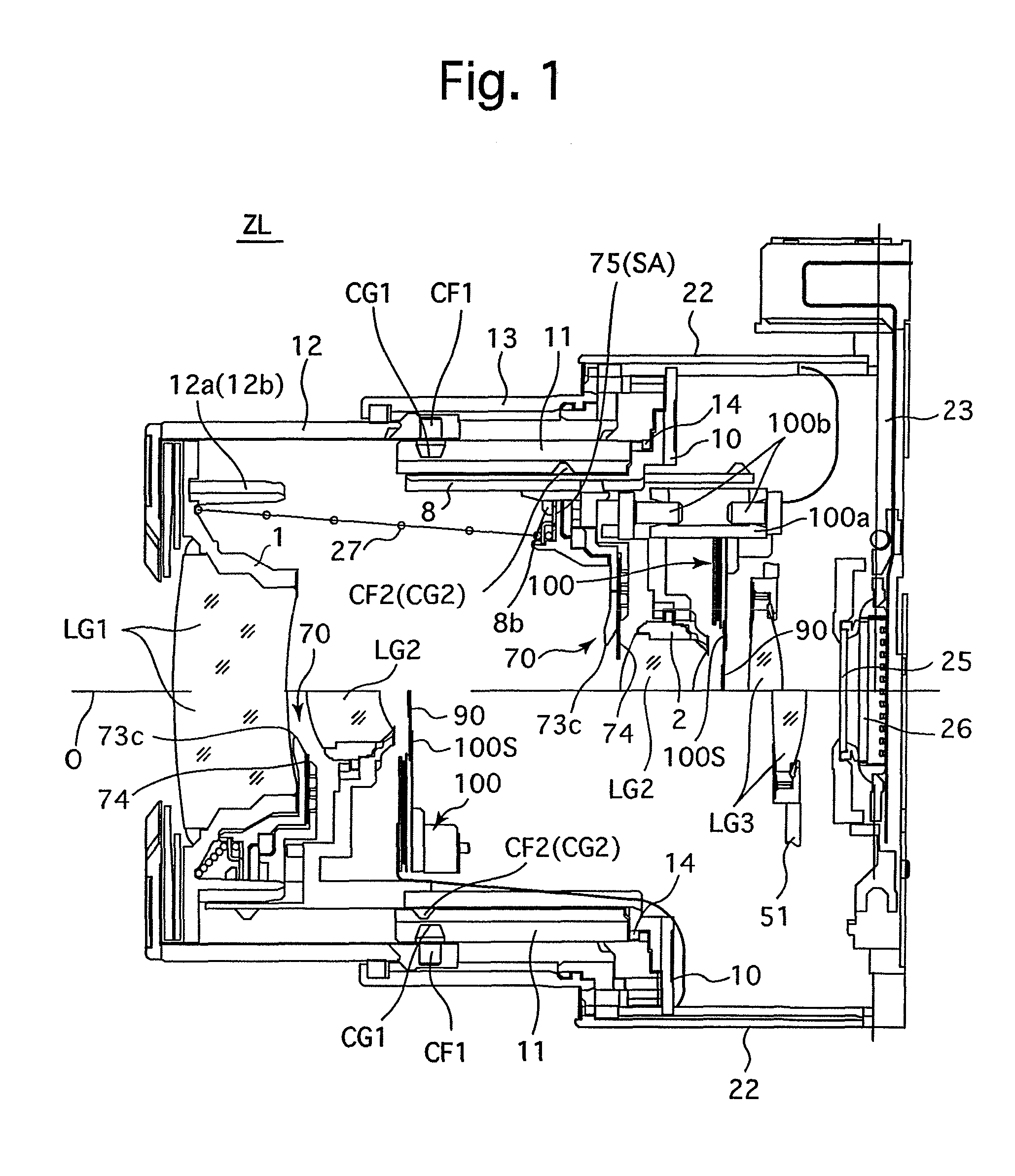
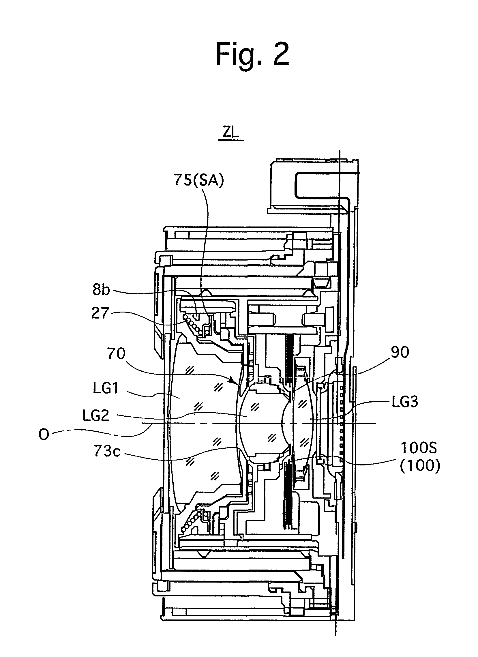
[0036]The brief description of the overall structure of an embodiment of a zoom lens barrel (zoom lens) ZL according to the present invention will be hereinafter discussed with reference to FIGS. 1 through 5. A photographing optical system installed in the zoom lens barrel ZL is provided with a first lens group LG1, a second lens group LG2, a third lens group (focusing lens group) LG3, a low-pass filter (optical filter) 25 and an image sensor 26, in that order from the object side. In the following descriptions, the optical axis direction refers to a direction along or parallel to a photographing optical axis O of this photographing optical system.

[0037]The low-pass filter 25 and the image sensor 26 are integrated as a single unit that is fixed to an image sensor holder 23, and the image sensor holder 23 is fixed to the back of a housing 22 of the zoom lens barrel ZL.

[0038]The zoom lens barrel ZL is provided with a third lens group frame 51 which holds the third lens group LG3. The ...


PUM


Abstract

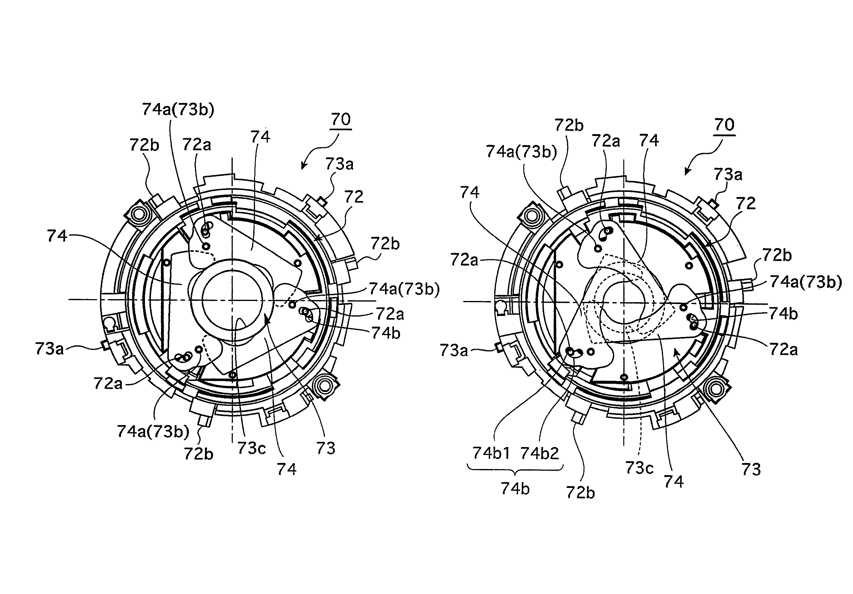
A zoom lens includes a variable aperture-stop mechanism positioned in front or behind an aperture-control lens group; a first rotation imparting member, which rotates an opening / closing ring of the variable aperture-stop mechanism by a relative movement between the variable aperture-stop mechanism and the first rotation imparting member in the optical axis direction so as to hold an adjustable aperture of the variable aperture-stop mechanism at a small aperture size when the aperture-control lens group moves within in the zooming range; and a second rotation imparting member, which rotates the opening / closing ring by a relative movement between the variable aperture-stop mechanism and the second rotation imparting member to open and hold the adjustable aperture at a large aperture size when the aperture-control lens group moves to the accommodated position, at which the aperture-control lens group is partly positioned in the adjustable aperture held at the large aperture size.

Description

BACKGROUND OF THE INVENTION[0001]1. Field of the Invention[0002]The present invention relates to a retractable zoom lens having a variable aperture-stop mechanism for varying a full-aperture F-number in accordance with the focal length of the zoom lens.[0003]2. Description of the Related Art[0004]In zoom lenses (zoom lens barrels) for compact cameras which include a lens shutter, specifically in such zoom lenses with a high zoom ratio, the maximum aperture size is varied in accordance with variations in the focal length of the zoom lens since harmful rays of light need to be shut out at the wide-angle extremity and the full-aperture F-number (full-aperture F value) needs to be reduced at the telephoto extremity.[0005]Variable aperture-stop mechanisms for making the aperture size adjustable are generally thick (large in size) in the optical axis direction, which is conventionally an obstacle to reduction in length of a retractable type of lens in its fully retracted state (accommodat...

Claims


Application Information

Patent Timeline
Patent Type & Authority Patents(United States)
IPC IPC(8): G02B9/08
CPCG02B5/005G02B7/10G03B9/24G03B17/04
Inventor NOMURA, HIROSHI
Owner HOYA CORP
Learn More