
Image forming apparatus and control method therefor

a technology of image forming apparatus and control method, which is applied in the direction of digital output to print units, instruments, digital computers, etc., can solve the problems of inconvenient users, inability to correctly restart the interrupted print job, and inability to acquire print data, so as to reduce unnecessary load

Inactive Publication Date: 2012-06-12
CANON KK
View PDF3 Cites 0 Cited by
  • Summary
  • Abstract
  • Description
  • Claims
  • Application Information

AI Technical Summary

Benefits of technology

This solution enables alteration of print data during a print job while minimizing network load by efficiently managing data storage and transmission, ensuring correct job restarts and reducing unnecessary network traffic.

Problems solved by technology

In that case, the second MFP cannot acquire the print data before being altered and cannot correctly restart the interrupted print job.
However, according to the first method, print data cannot be altered by the first MFP during execution of the print job for the print data drawn from the first MFP, which is inconvenient for users.
With the second method, since print data is saved from the second MFP to another location via a network such as LAN, it takes much time to save the print data and unnecessary load is applied to the network.

Method used


Image

  • Image forming apparatus and control method therefor
  • Image forming apparatus and control method therefor
  • Image forming apparatus and control method therefor

Examples


first embodiment

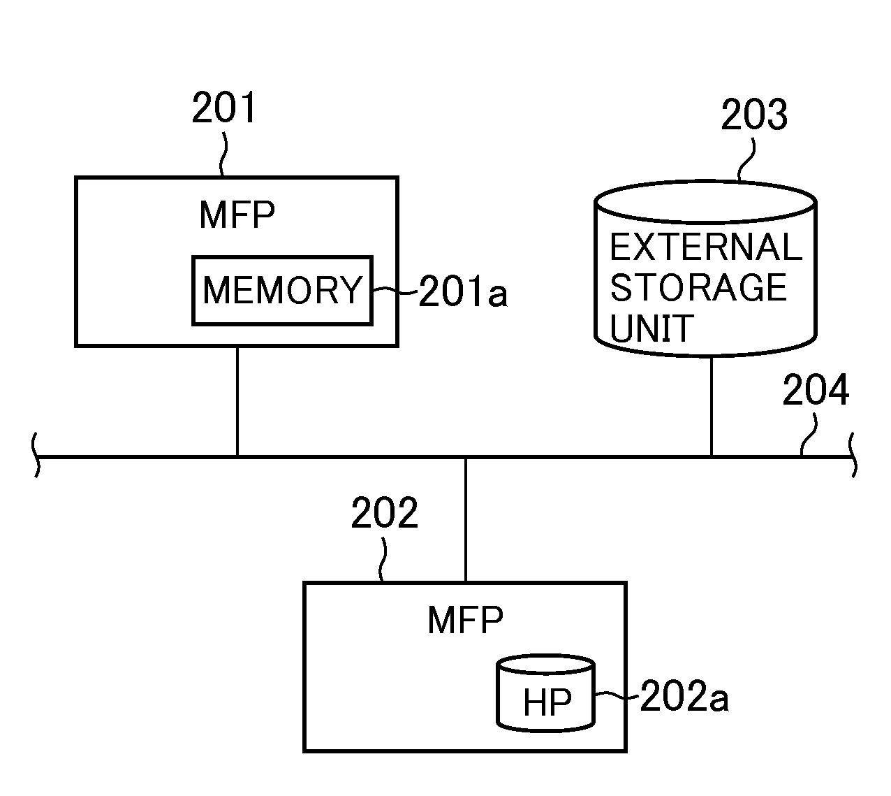
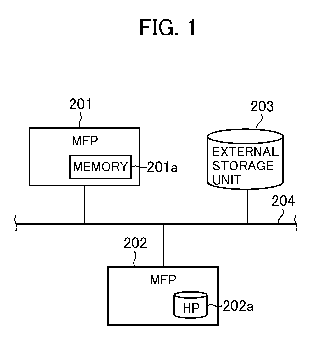
[0033]FIG. 1 shows in block diagram the construction of a system including an image forming apparatus according to a first embodiment of this invention.

[0034]As shown in FIG. 1, the system includes a plurality of, e.g., two multi-function peripherals (hereinafter referred to as the MFPs) 201, 202 and an external storage unit 203. The MFPs 201, 202 and the storage unit 203 are connected to a network, e.g., a LAN (local area network) 204 to which servers, client computers, etc. (none of which are shown) are connected. Each of the MFPs in this embodiment is an example image forming apparatus. The image forming apparatus is not limited to the MFP, but may be a printer, a scanner, a facsimile machine, a copying machine, a personal computer, a cellar phone, or the like.

[0035]Each of the MFPs 201, 202 has multiple functions, such as functions of facsimile, data transfer, scanner, printer and copier and is able to perform various jobs using these functions. The MFP 201 has a memory 201a of ...

second embodiment

[0074]In the following, a second embodiment of this invention is described with reference to FIGS. 8 to 13.

[0075]This embodiment differs from the first embodiment in that copy data of the print data is stored into the external storage unit 203 or the HD 202a of the MFP 202 according to whether or not the print data is altered, if free space of the memory 201a of the MFP 201 is less than the capacity required for execution of an interruption job. In other respect, this embodiment is the same in construction as the first embodiment, and therefore a description of the common structure is omitted.

[0076]With reference to FIGS. 8A to 8E, the outline of pull print in this embodiment is first described. FIGS. 8A to 8E schematically show in the second embodiment how requests and print data are exchanged between the MFPs 201, 202 and the external storage unit 203 and how print data and its copy data are stored in the MFPs 201, 202.

[0077]As shown in FIG. 8A, print data 601 is stored in the HD ...


PUM


Abstract

An image forming apparatus that permits alteration of print data during execution of a print job for the print data stored in an external apparatus. Upon generation of an interruption job during execution of the print job for the print data, an MFP suspends the print job. If free space in a memory is less than the capacity required for execution of the interruption job, the MFP erases the print data in the memory and carries out the interruption job. When the interruption job is completed, the MFP transmits to another MFP a request for transmission of copy data of the print data and restarts the print job for the copy data of the print data transmitted from the other MFP in response to the transmission request.

Description

BACKGROUND OF THE INVENTION[0001]1. Field of the Invention[0002]The present invention relates to an image forming apparatus capable of drawing, from an external apparatus, print data stored therein and executing a print job for the print data, and relates to a control method for the image forming apparatus.[0003]2. Description of the Related Art[0004]Some of multi-function peripherals having multiple functions, such as a printer function and a scanner function, has a hard disk unit (HD) for storage of print data. Print data stored in the HD of such a multi-function peripheral (hereinafter referred to as the first MFP) can be printed by a second MFP having a memory for temporary storage of print data. This type of printing is called pull print. To perform the pull print, the second MFP draws print data from the first MFP and temporarily stores the print data until completion of printing the print data. Thus, it is not essentially required for the second MFP to have an HD.[0005]During...

Claims


Application Information

Patent Timeline
Patent Type & Authority Patents(United States)
IPC IPC(8): G06F15/00G06F3/12G06K1/00
CPCH04N1/00222H04N1/2166H04N1/32448G06F3/122G06F3/1258G06F3/1285H04N2201/216H04N2201/218H04N2201/3295
Inventor TAKEUCHI, TOMOYUKI
Owner CANON KK
Learn More