
Differential forwarding in address-based carrier networks

a carrier network and address-based technology, applied in the field of differential forwarding in address-based carrier networks, can solve the problems of incompatibility of conventional switched ethernet networks with carriers' requirements for providing guaranteed services, inability to meet the requirements of carriers, and unstable and complex standards of mpls

Inactive Publication Date: 2012-06-05
RPX CLEARINGHOUSE
View PDF13 Cites 5 Cited by
  • Summary
  • Abstract
  • Description
  • Claims
  • Application Information

AI Technical Summary

Benefits of technology

[0016]The mappings are to selected output ports of the one or more nodes. By using the combination of address AND identifier, the mappings enable data frames belonging to different connections to be forwarded differentially (ie forwarded on different output ports) despite the different connections potentially having the same destination (or source) node. This enables flexibility in routing connections—eg the ability to perform traffic engineering. The reader should note that the term address is used in this document to denote any means of identifying a network node or an ingress or egress interface of a network node, or any sub unit of a network node, for example a port card or an encapsulation function of a network node.
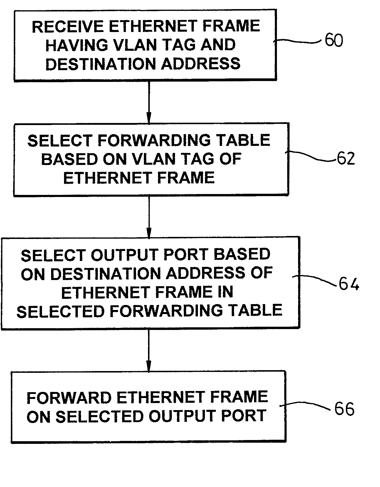
[0051]According to a seventh aspect of the present invention, there is provided a method of data traffic engineering in a frame-based network, the method comprising the following steps: establishing a first and second connections in the network passing through a common switching node of the network, configuring the switching node to forward data frames differently in dependence on differences in either a destination address or an identifier of the data frames, thereby enabling data traffic engineering.

Problems solved by technology

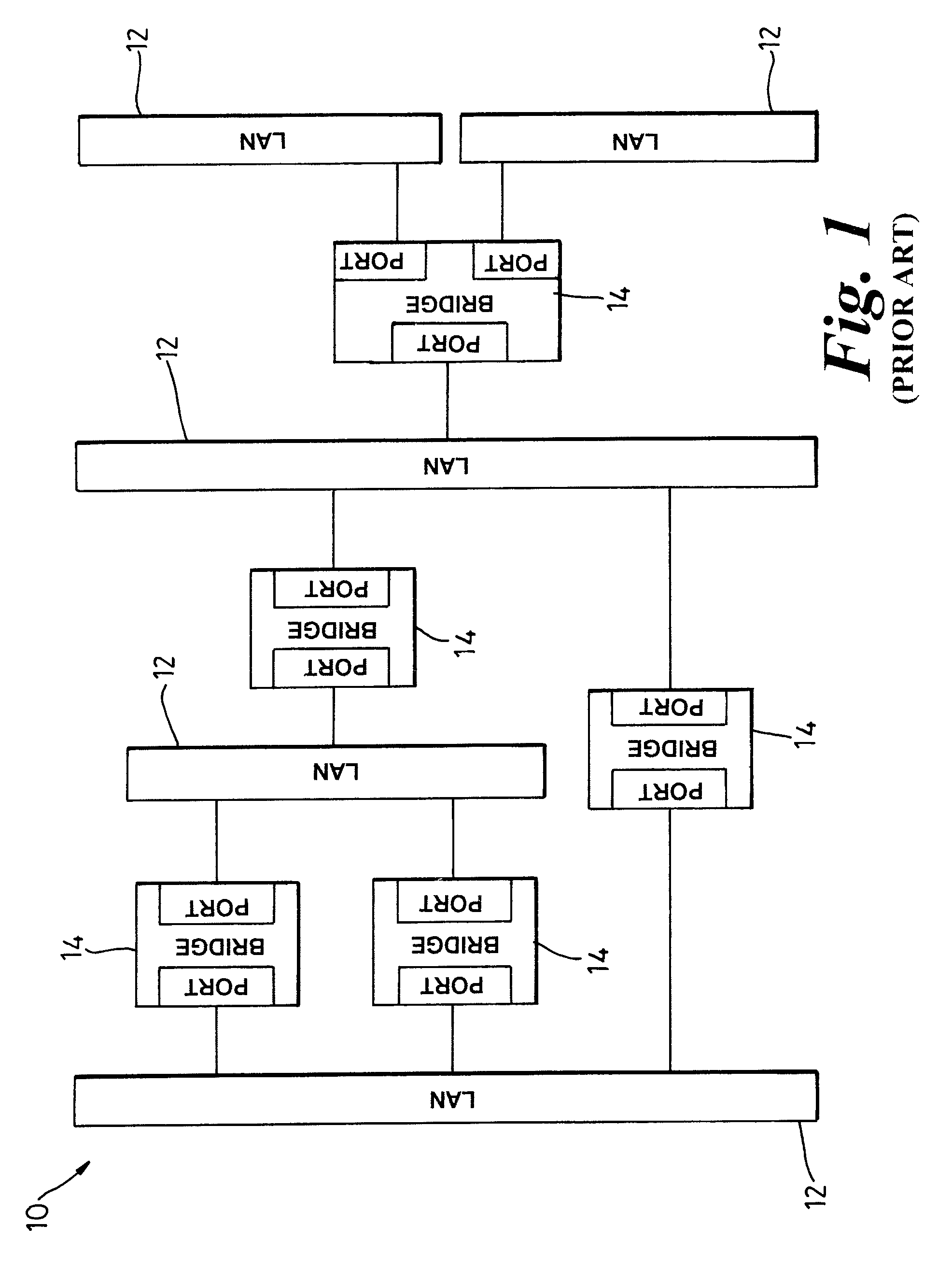
Packet-switched networks such as Internet Protocol (IP) or Ethernet networks are intrinsically connectionless in nature and as a result suffer from Quality of Service (QoS) problems.
However, MPLS is a relatively unstable and complex standard and carriers ideally desire an alternative.
However, the behaviour of conventional switched Ethernet networks is incompatible with carriers' requirements for providing guaranteed services to customers.
As a consequence, conventional Ethernet networks do not have support for network-wide load balancing, suffer from resiliency problems and cannot support traffic engineering.
Further the impact of a single failure with respect to the overall load carried can be significant.
However the size of the standard VLAN tag is limited to 12 bits, which in turn limits the scale of the network and the number of partitions of component LANs to 4094, where two VLAN tags are reserved with special meaning not for general assignment.
However, one problem with the method proposed in draft-kawakami-mpls-lsp-vlan-00.txt is that only a maximum of 4094 unique VLAN tags are definable in 802.1Q compliant equipment.
This still limits the flexibility and increases the complexity of provisioning connections across the network.
Another problem is that connections may not easily be re-routed once provisioned without in general creating transitory loops.
Another problem is that since the Frame Check Sequence (FCS) in Ethernet frames is computed over both the payload and header portions of the frame, every time a VLAN tag (ie a label) is swapped at the ingress or egress point of a LSP, the FCS needs to be recomputed since the VLAN tag will have changed.
Moreover, during the interval from when the original FCS is removed and the new FCS added, the frame is vulnerable to corruption without the protection of any FCS.
Yet another problem with the ‘label-swapping’ approach proposed in draft-kawakami-mpls-lsp-vlan-00.txt is that it requires a “chain of correctness”, in that forwarding relies on each local label-forwarded link on the LSP being correct.

Method used


Image

  • Differential forwarding in address-based carrier networks
  • Differential forwarding in address-based carrier networks
  • Differential forwarding in address-based carrier networks

Examples


Embodiment Construction

[0069]Embodiments of the present invention are described below by way of example only. These examples represent the best ways of putting the invention into practice that are currently known to the Applicant although they are not the only ways in which this could be achieved.

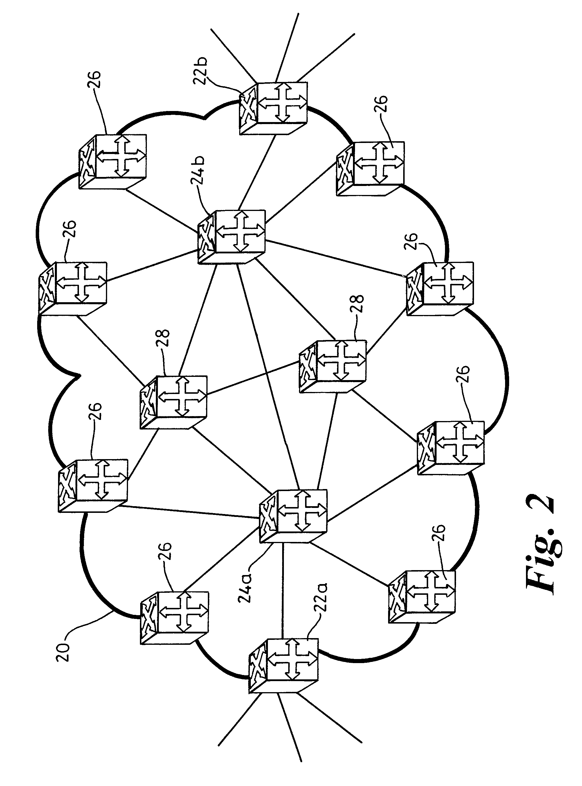
[0070]To support guaranteed QoS to customers, what is required is:[0071]1) an at least partially meshed carrier network;[0072]2) the ability to establish explicitly routed connections across the carrier network between any two edge nodes (traffic engineering); and[0073]3) the ability to enforce any bandwidth restrictions and / or forwarding rules applied to the connections.

[0074]The present invention is primarily concerned with enabling requirements 1) and 2) above in frame-based networks such as Ethernet networks. Requirement 3) may be achieved for example using conventional mechanisms such as admission control in either or both of the control plane and at the ingress nodes of connections (trusted-edge policing). ...


PUM


Abstract

The invention relates to enabling differential forwarding in address-based carrier networks such as Ethernet networks. There is described a method of and connection controller for establishing connections (76, 77) in a frame-based communications network comprising nodes (71-75 and 78) such as Ethernet switches. The connections are established by configuring, in various of the nodes, mappings for forwarding data frames, such as Ethernet frames. The mappings are from a combination of a) a destination (or source) address corresponding to a destination (or source) node (73) of the connection and b) an identifier, such as a VLAN tag. The mappings are to selected output ports of the various nodes. By using the combination of destination (or source) address AND identifier, the mappings enable data frames belonging to different connections (76, 77) to be forwarded differentially (ie forwarded on different output ports) at a node (75) despite the different connections having the same destination node. This enables flexibility in routing connections and the ability to perform traffic engineering.

Description

RELATED APPLICATIONS[0001]This application is a continuation of U.S. patent application Ser. No. 10 / 593,108, with a 35 U.S.C. 371 date of May 21, 2007, which is the National filing of International Application No. PCT / GB2005 / 001332, filed Apr. 6, 2005 which claims its priority to U.S. patent application Ser. No. 10 / 818,865 filed Apr. 6, 2004.FIELD OF THE INVENTION[0002]The present invention relates to methods of, software for and apparatus for differential forwarding in address-based carrier networks. In particular, but not exclusively, the present invention relates to methods of, software for and apparatus for differential forwarding and establishing connections in intrinsically connectionless carrier networks which address-based forwarding, such as Ethernet or IP networks.BACKGROUND TO THE INVENTION[0003]For many years now, telecommunications carriers have been deploying packet-switched networks in place of or overlaid upon circuit-switched networks for reasons of efficiency and e...

Claims


Application Information

Patent Timeline
Patent Type & Authority Patents(United States)
IPC IPC(8): H04L12/28
CPCH04L12/4645H04L45/00H04L45/54H04L45/64H04L45/66H04L49/205H04L45/72H04L41/0823H04L45/16H04L49/253H04L49/254H04L49/351H04L49/354
Inventor FRISKNEY, ROBERTBRAGG, NIGELPARRY, SIMONASHWOOD SMITH, PETERALLAN, DAVIDBRUECKHEIMER, SIMON
Owner RPX CLEARINGHOUSE
Learn More