
Image forming apparatus capable of discharging stacked sheets

a technology of image forming apparatus and stacked sheets, which is applied in the direction of electrographic process apparatus, instruments, optics, etc., can solve the problems of reducing job efficiency, and achieve the effect of improving productivity, not reducing performance wastefully, and reducing delay tim

Active Publication Date: 2012-05-29
SHARP KK
View PDF12 Cites 4 Cited by
  • Summary
  • Abstract
  • Description
  • Claims
  • Application Information

AI Technical Summary

Benefits of technology

[0008]An object of the present invention is to provide an image forming apparatus which improves its productivity and does not reduce its performance wastefully even in a case where (i) the image forming apparatus and a post-processing device constitute an image forming system and (ii) image forming jobs are performed in succession. In the image forming apparatus of the present invention, in a case where image forming jobs are performed in succession, (i) it is not necessary to delay an image formation to be performed for the second image forming job so that time required to perform a post-process for the first image forming job followed by the second image forming job is secured; or (ii) if the delay is inevitable, the delay time is reduced as much as possible.
[0013]That is, if time required to perform a post-process for the first image forming job is within the delay time gained by the delay of the first sheet for the second image forming job, it is possible to perform the second image forming job subsequently after the first image forming job, without stopping the image formation to be performed for the second image forming job. Further, even if the time required to perform the post-process for the first image forming job exceeds the delay time gained by the delay of the first sheet for the second image forming job, it is possible to reduce time in which the image formation to be performed for the second image forming job is stopped.
[0014]Thus, constituting an image forming system by using an image forming apparatus according to the present invention makes it possible to realize an image forming system which has a high productivity and does not reduce performance of an image forming apparatus wastefully.
[0019]That is, if time required to perform a post-process for the first image forming job is within the delay time gained by the delay of the first image forming job, it is possible to perform the second image forming job subsequently after the first image forming job, without stopping the image formation to be performed for the second image forming job. Further, even if the time required to perform the post-process for the first image forming job exceeds the delay time gained by the delay of the first sheet for the second image forming job, it is possible to reduce time in which the image formation to be performed for the second image forming job is stopped.
[0020]Thus, constituting an image forming system by using an image forming apparatus according to the present invention makes it possible to realize an image forming system which has a high productivity and does not reduce performance of an image forming apparatus wastefully.

Problems solved by technology

The arrangement in Patent Document 1, however, does not solve the following problem: in a case where image forming jobs are performed in succession, job efficiency is decreased because the image forming apparatus delays starting the second image forming job and causes the second image forming job to be in a stand-by state so that time required to perform a post-process for the first image forming job is secured.

Method used


Image

  • Image forming apparatus capable of discharging stacked sheets
  • Image forming apparatus capable of discharging stacked sheets
  • Image forming apparatus capable of discharging stacked sheets

Examples


Embodiment Construction

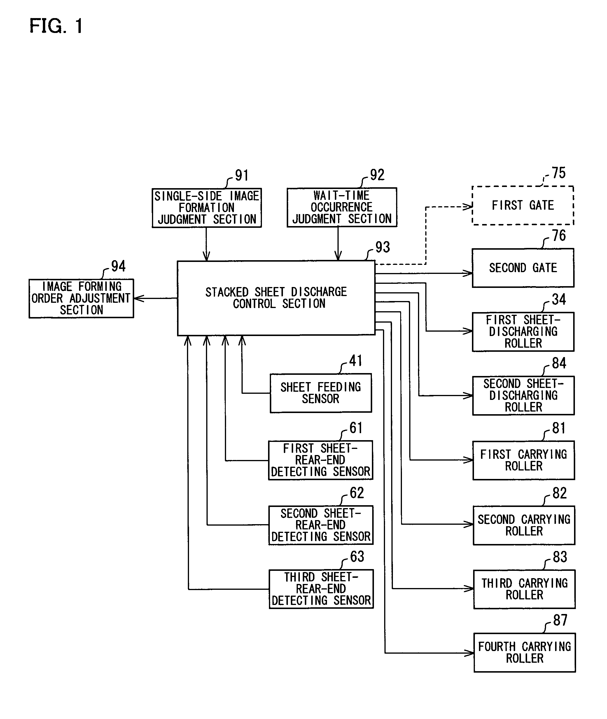
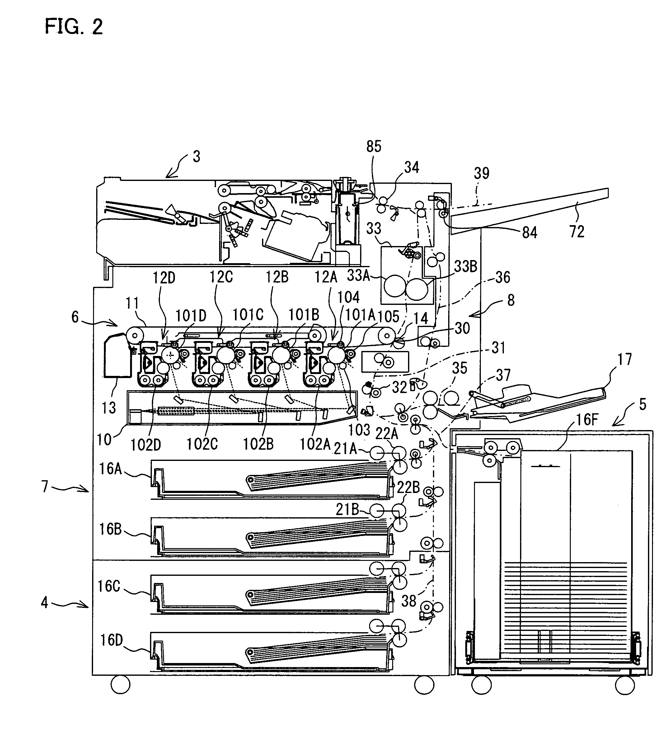
[0038]The following describes, with reference to FIG. 1 through FIG. 16, one embodiment of the present invention. Firstly, an arrangement of an image forming system 1 according to one embodiment of the present invention is described with reference to FIG. 2. FIG. 2 is an explanatory view illustrating the arrangement of the image forming system 1.

[0039]The image forming system 1 is constituted by adding, to an image forming apparatus 2, (i) a post-processing device 3 and (ii) two sheet feeding devices 4 and 5. The description herein deals with, as an example, the image forming apparatus 2 provided with (i) the post-processing device 3 and (ii) the two sheet feeding devices 4 and 5. However, an image forming system according to the present invention only needs to be provided with at least an image forming device and a post-processing device provided to the image forming device.

[0040]The image forming apparatus 2 forms an image in multi colors or in a mono color selectively by means of...


PUM


Abstract

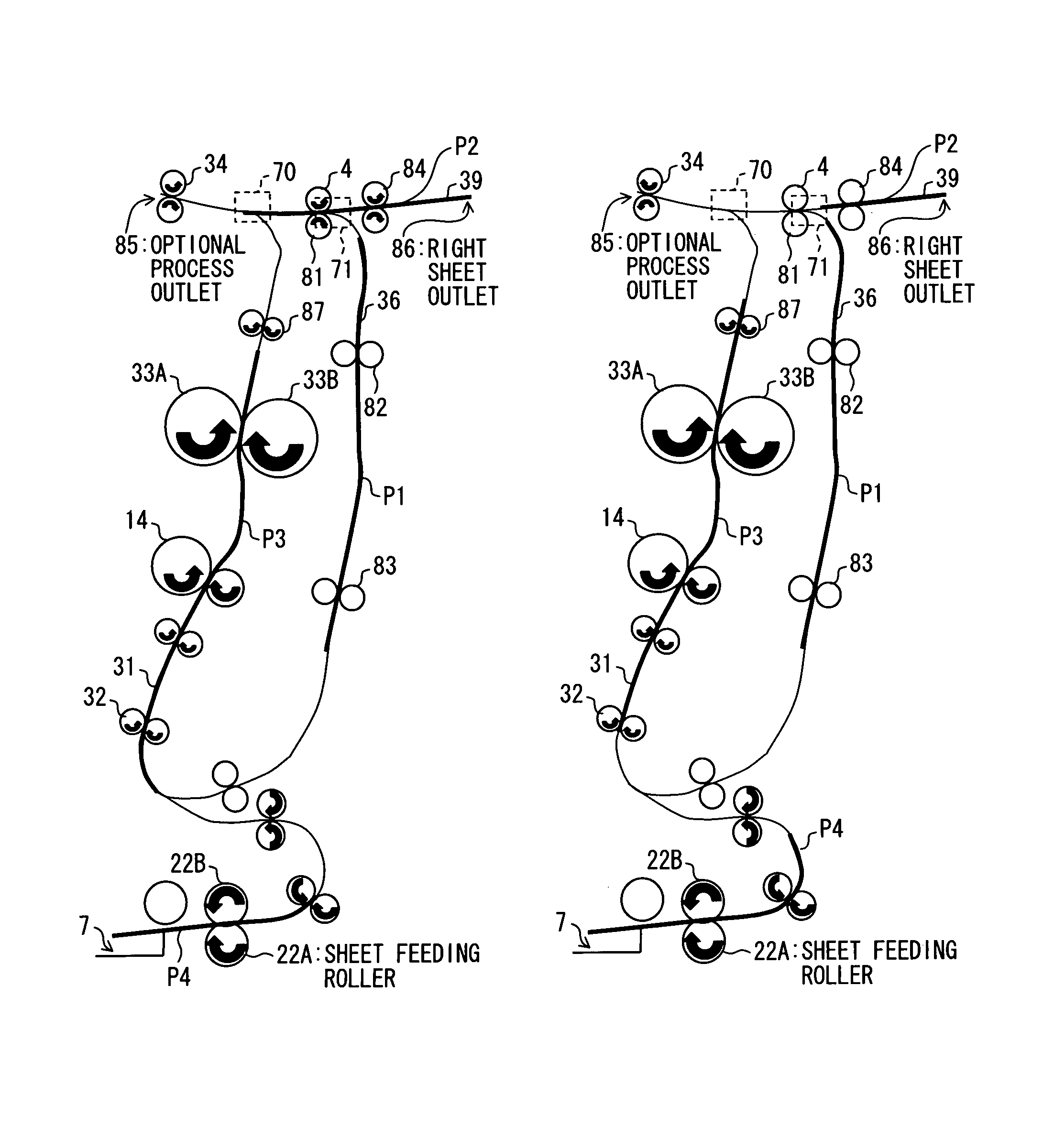
An image forming apparatus performs a single-side image formation such that, when a delay is needed, a stacked sheet discharge control section controls a sheet carrying mechanism so that: a first sheet (for a second imaging job) to be discharged after passing a first sheet-discharging roller via a first sheet-carrying path is directed to another carrying path without being discharged, and is stood by therein. The first sheet and a second sheet (for the second imaging job) which is carried to the first sheet-discharging roller via the first sheet-carrying path after the first sheet, then are concurrently discharged overlappingly. This eliminates needs for delaying image formation for the second imaging job, and for securing time for post-process for the first imaging job. Even if a delay is inevitable, this reduces the delay time greatly and improves the productivity of the image forming apparatus, without reducing its performance wastefully.

Description

[0001]This Nonprovisional application claims priority under U.S.C. §119(a) on Patent Application No. 314008 / 2007 filed in Japan on Dec. 4, 2007, the entire contents of which are hereby incorporated by reference.FIELD OF THE INVENTION[0002]The present invention relates to a technique for improving productivity of an image forming system realized by adding a post-processing device to an image forming apparatus.BACKGROUND OF THE INVENTION[0003]Some image forming apparatuses are connectable to, as an option, a post-processing device which performs a post-process on a sheet discharged from the image forming apparatuses. An image forming apparatus provided with a post-processing device constitutes an image forming system. Examples of the post-process encompass: stapling sheets; discharging a sheet to a designated sheet output tray out of a plurality of sheet output trays; and offsetting a sheet discharging position on a sheet output tray.[0004]Patent Document 1 (Japanese Unexamined Patent...

Claims


Application Information

Patent Timeline
Patent Type & Authority Patents(United States)
IPC IPC(8): G03G15/00
CPCG03G15/231G03G15/6552G03G2215/00421G03G2215/00924
Inventor TANAKA, KENJI
Owner SHARP KK
Learn More