
DSM enabling of electro mechanically controlled refrigeration systems

a technology of electromechanical control and refrigeration system, applied in the field of energy management, can solve the problems affecting the efficiency of electromechanical control refrigerators, etc., and achieve the effect of reducing the peak power consumption of electromechanically controlled refrigerators

Active Publication Date: 2012-05-22
HAIER US APPLIANCE SOLUTIONS INC
View PDF8 Cites 22 Cited by
  • Summary
  • Abstract
  • Description
  • Claims
  • Application Information

AI Technical Summary

Benefits of technology

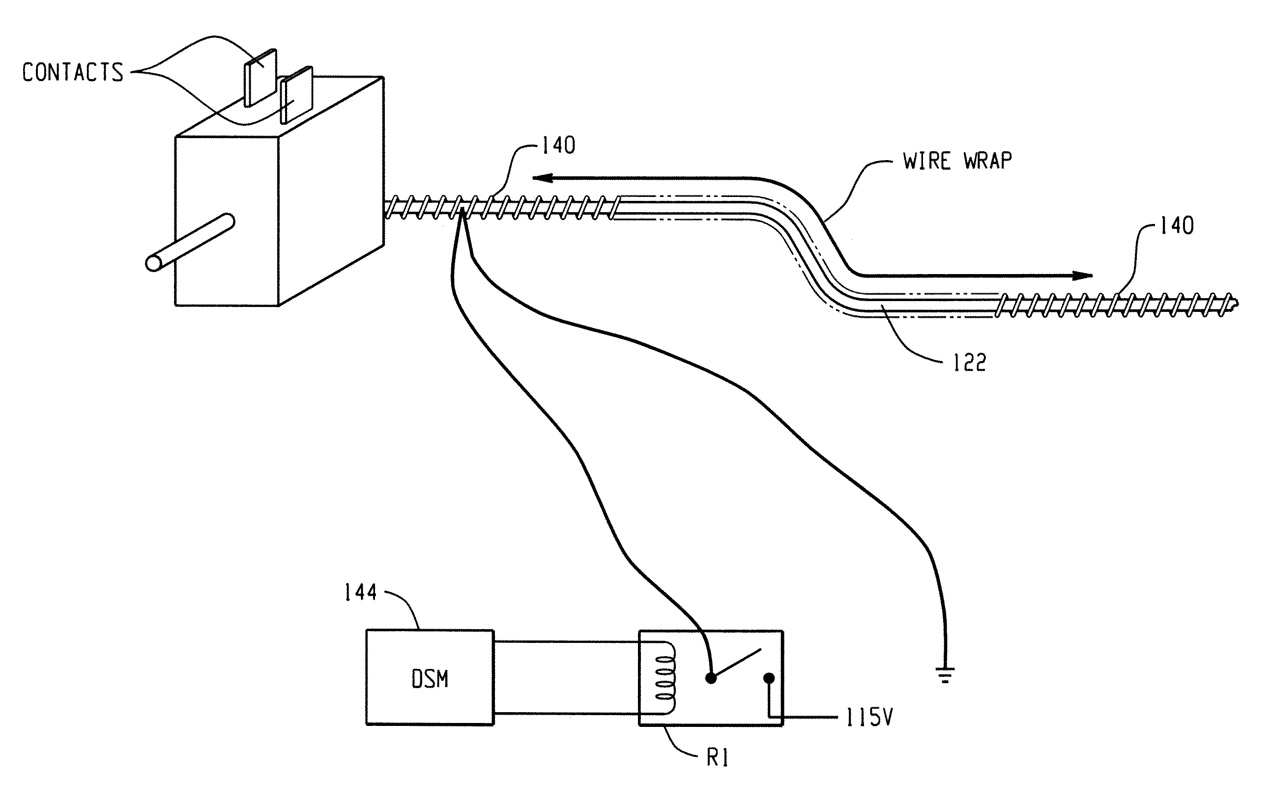
[0008]According to one aspect of the present disclosure, a system for reducing the peak power consumption in an electromechanically controlled refrigerator is provided. The system comprises a cold control device including a housing and a counter spring having at least one spring tension position corresponding to a temperature set point, a bourdon tube having a first end comprising a rubber diaphragm operatively associated with the counter spring, and a second end, opposite the first end, located in the compartment, wherein the counter spring is capable of providing a force against the diaphragm, and a DSM switching device operatively controlled by an associated DSM module. The DSM module is configured to receive a signal indicative of at least one of a peak or non-peak demand period of an associated utility.
[0009]According to another aspect of the present disclosure, a method of reducing peak power consumption in an electromechanically controlled refrigerator having at least one compartment is provided. The method comprises providing a cold control, calibrated to a first temperature set point with a counter spring having various spring tension positions, each spring tension position being correlated to a different temperature set point, associating a bourdon tube diaphragm with the counter spring, such that the counter spring applies force against the diaphragm, operationally associating the counter spring position with a DSM switching device, wherein the switching device is controlled by an associated DSM module that receives signals indicative of at least one of a peak and non-peak demand period of an associated utility, and shifting the spring platen position in response to the signal to increase or decrease force against the diaphragm, thereby one of increasing and decreasing the temperature set point of the cold control.
[0010]According to yet another aspect of the present disclosure, a system for reducing the power consumption in an electromechanically controlled refrigerator during periods of peak power demand is provided. The system comprises a cold control device having a counter spring with at least one spring tension position, the cold control being calibrated to a temperature set point, a bourdon tube operationally associated with the counter spring, such that the counter spring is configured to impart a force against the diaphragm determinative of the setpoint temperature, and a DSM switching device configured to cause the spring platen position to shift based on a signal received from an associated DSM module indicative of at least one of a peak and non-peak demand period of an associated utility.

Problems solved by technology

Many utilities are currently experiencing a shortage of electric generating capacity due to increasing consumer demand for electricity.
Although these systems are capable of being run automatically according to demand period, a user may choose to override the system and run a device normally, or delay the operation of the system for a particular period of time.
However, such a DSM / SAM add-on device will generally cut off the power to an entire appliance.
The microcontroller may additionally delay a scheduled defrost if the defrost is set to occur during a peak demand period.
While electronically controlled refrigerators can adjust energy usage in response to a “high demand”, many refrigerators include less technically sophisticated controls that do not use a microprocessor.

Method used


Image

  • DSM enabling of electro mechanically controlled refrigeration systems
  • DSM enabling of electro mechanically controlled refrigeration systems
  • DSM enabling of electro mechanically controlled refrigeration systems

Examples


Embodiment Construction

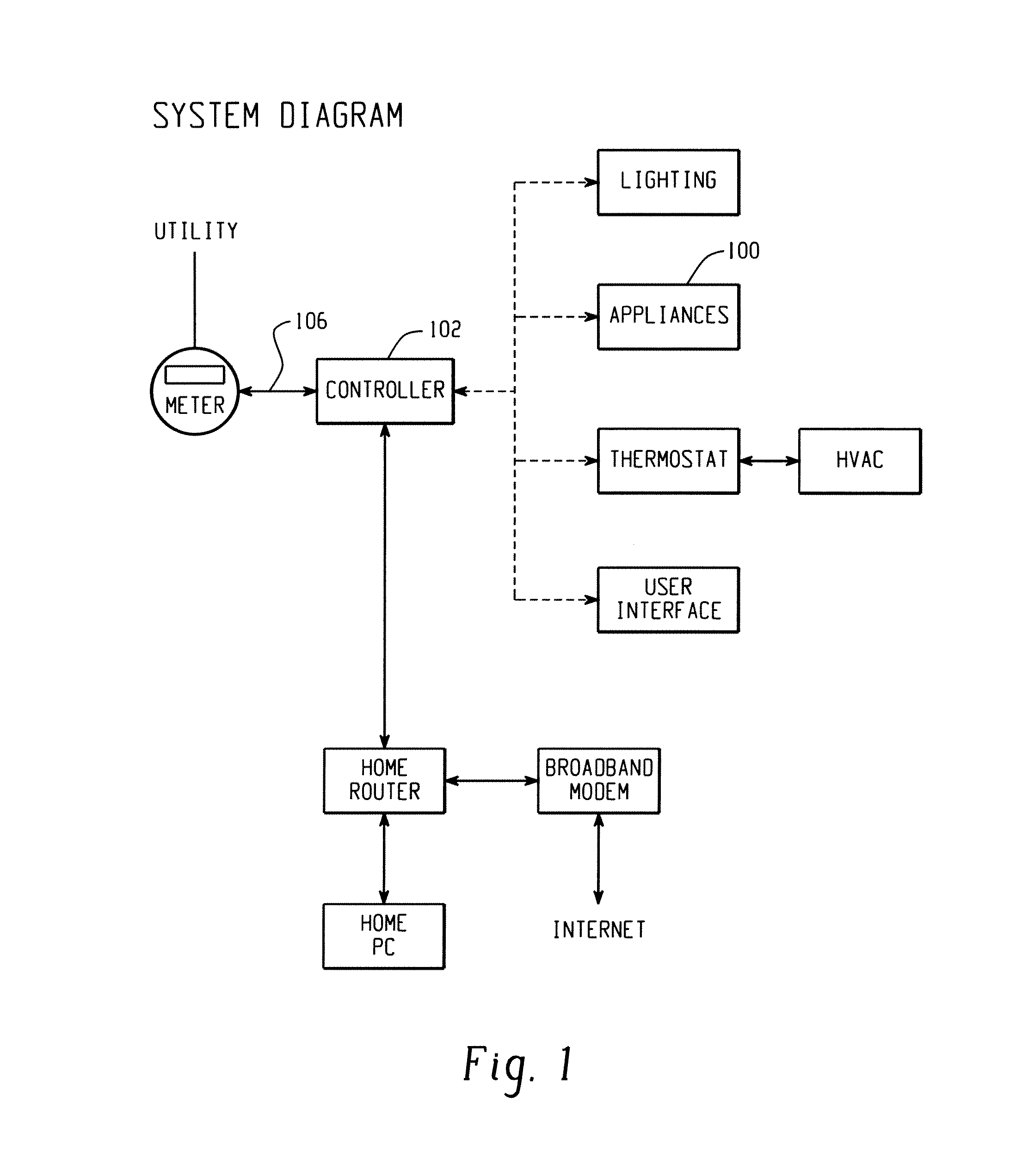
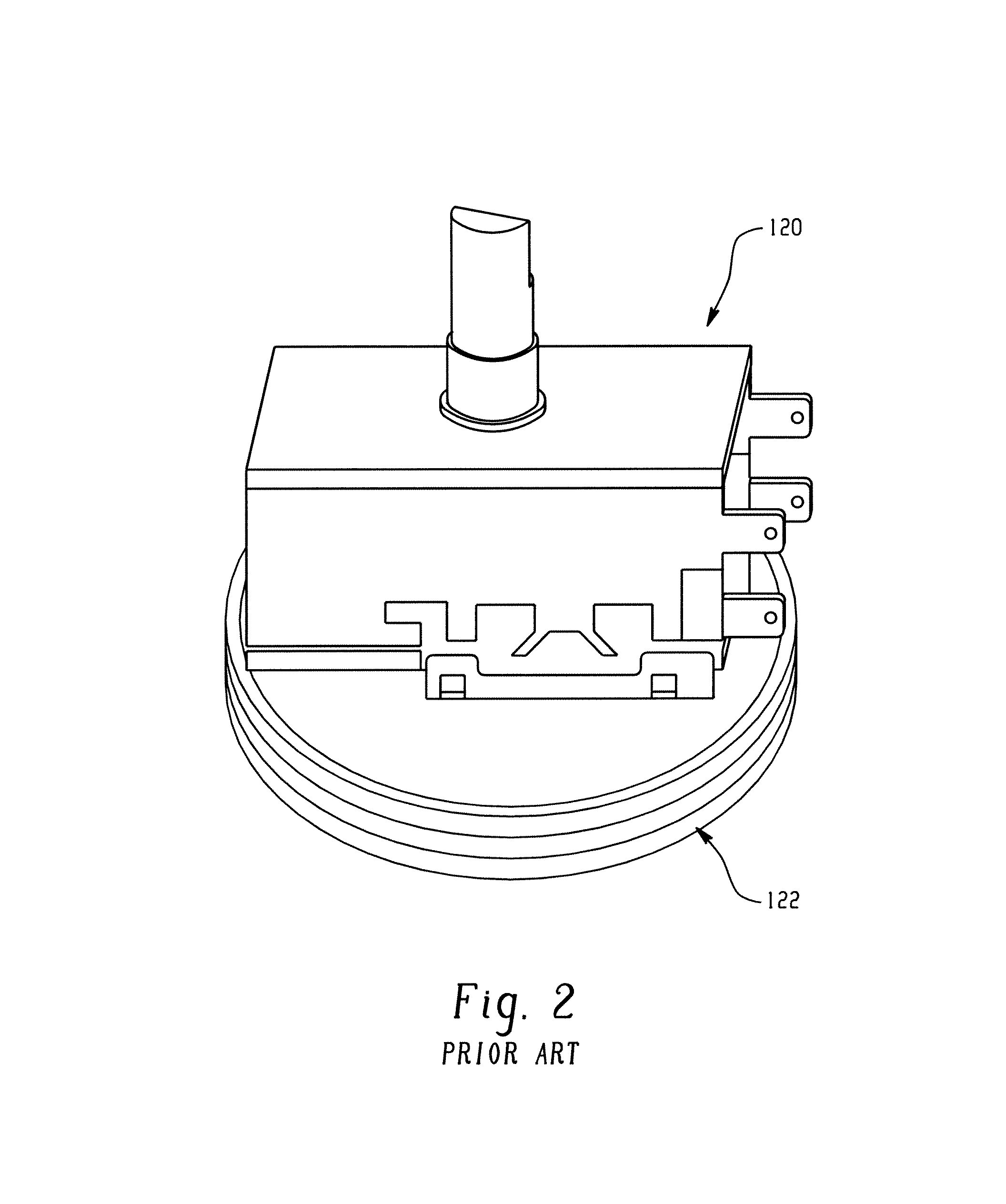
[0021]An exemplary embodiment of an energy management system for household appliances 100 is illustrated in FIG. 1. An electronic controller 102 is provided for communicating with a utility meter and reducing power consumption in response to a signal 106 indicative of a peak demand period. Electromechanically controlled refrigerators, according to one aspect of the present disclosure, include a cold control 120 to control the temperature of the refrigerator compartments, which is depicted in FIG. 2. A cold control 120 is a temperature control incorporating a single pole, single throw switch with an associated set of electrical contacts for turning a refrigerator's compressor and fans concurrently on and off. A bourdon tube 122 is associated with the cold control 120 to sense temperature increases and decreases in a refrigerator compartment. As introduced above, a bourdon tube 122 is a hollow tube filled with refrigerant or an inert gas and placed in the airstream of the compartment ...


PUM


Abstract

A system for reducing the peak power consumption in an electromechanically controlled refrigerator is provided. The system comprises a cold control device including a housing and a counter spring having at least one spring tension position corresponding to a temperature set point, a bourdon tube having a first end comprising an elastomeric diaphragm operatively associated with the counter spring, and a second end, opposite the first end, located in the compartment, wherein the counter spring is capable of providing a force against the diaphragm, and a DSM switching device operatively controlled by an associated DSM module. The DSM module is configured to receive a signal indicative of at least one of a peak or non-peak demand period of an associated utility.

Description

BACKGROUND OF THE DISCLOSURE[0001]This disclosure relates to energy management, and more particularly to energy management of household refrigeration appliances. The disclosure finds particular application to adapting electromechanically controlled refrigerators for operation in home energy management systems.[0002]Many utilities are currently experiencing a shortage of electric generating capacity due to increasing consumer demand for electricity. Currently utilities charge a flat rate, but with increasing cost of fuel prices and high energy usage at certain parts of the day, utilities have to buy more energy to supply customers during peak demand, which causes prices to rise during these times. If peak demand can be lowered, then a potential huge cost savings can be achieved and the peak load that the utility has to accommodate is lessened. In order to reduce high peak power demand, many utilities have instituted time of use (TOU) metering and rates which include higher rates for ...

Claims


Application Information

Patent Timeline
Patent Type & Authority Patents(United States)
IPC IPC(8): F25B41/04G01M1/38G05B13/00G05B15/00G05D23/00
CPCG05D23/1904G05D23/1923G05D23/1951F25D21/006F25D29/00F25D2600/02
Inventor BESORE, JOHN K.
Owner HAIER US APPLIANCE SOLUTIONS INC
Learn More