Method for activating a workpiece manipulator of a machine tool

a technology of workpiece manipulator and machine tool, which is applied in the field of activating the workpiece manipulator of the machine tool, can solve the problems of increasing the non-productive time of the machine, and achieve the effects of reducing the non-productive period

Inactive Publication Date: 2012-05-15
ANGER MACHINING
View PDF20 Cites 0 Cited by
  • Summary
  • Abstract
  • Description
  • Claims
  • Application Information

AI Technical Summary

Benefits of technology

[0008]Based on a technique of the kind mentioned initially, the invention is based on the object of providing a method for activating a workpiece manipulator of a machine tools which on the one hand enables the machining of a workpiece with an increased number of tools under the shortest possible machining times, i.e. minimized non-productive periods, and on the other hand allows a rapid and secure return of the workpiece manipulator with the workpiece to the starting position of the machine in the event of a termination of machining.
[0010]An automatic return of the workpiece manipulator plus workpiece to the machine starting position is thus easily possible with these measures in accordance with the invention, without damaging tools associated with other machining steps and without damaging the tool spindles associated with these machining steps. Machining is principally subdivided into several machining steps, with one machining step being associated with one machining tool in the simplest of cases. The starting position in the respective machining tool can be accessed especially in a direct and secure manner from the machine starting position or from the end position of a preceding machining step in another tool without having to fear any damage to the workpiece or tools and tool spindles. Based on these starting positions, the machining is started on the respective tool and in the case of a termination of machining as a result of emergency stop or tool breakage or the like the workpiece manipulator plus workpiece are moved back along the path of movement to the starting position associated to this machining step, from which the workpiece manipulator plus workpiece can optionally be displaced without any problems in an automated manner to the machine starting position. It is understood that also the entire path of movement in all tools up to the machine starting position can be travelled back.
[0011]With these simple measures it is possible to realize an automated free passage of tools in the event of machining termination also on already existing machine tools by implementing a respective control. The free passage can be realized in an especially simple and cost-effective manner with the measures in accordance with the invention for machine tools that are newly designed. Since the workpieces produced with these machine tools usually concern pieces of medium or larger series, workpiece rejects which are optionally produced by the return travel can usually be accepted without any problems. This does not apply however to additionally increased non-productive times of the machine which are produced by collisions of the workpiece with intact tools or machining spindles and which optionally lead to a change of the same.
[0015]In order to further minimize the damage probability of tools or tool spindles it is recommended that the workpiece with the tool manipulator is moved successively to a plurality of fixed tool spindles positioned in a frame-like rack at different positions, with the tool spindles being movable from a retracted idle position to an extended working position for machining the workpiece.

Problems solved by technology

This does not apply however to additionally increased non-productive times of the machine which are produced by collisions of the workpiece with intact tools or machining spindles and which optionally lead to a change of the same.

Method used


Image

  • Method for activating a workpiece manipulator of a machine tool
  • Method for activating a workpiece manipulator of a machine tool
  • Method for activating a workpiece manipulator of a machine tool

Examples


Embodiment Construction

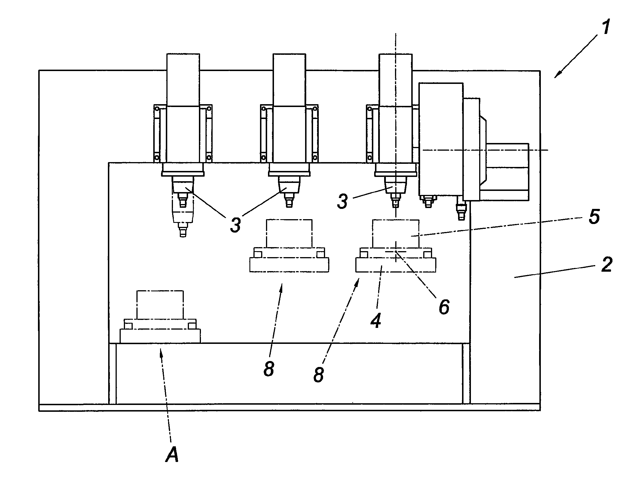
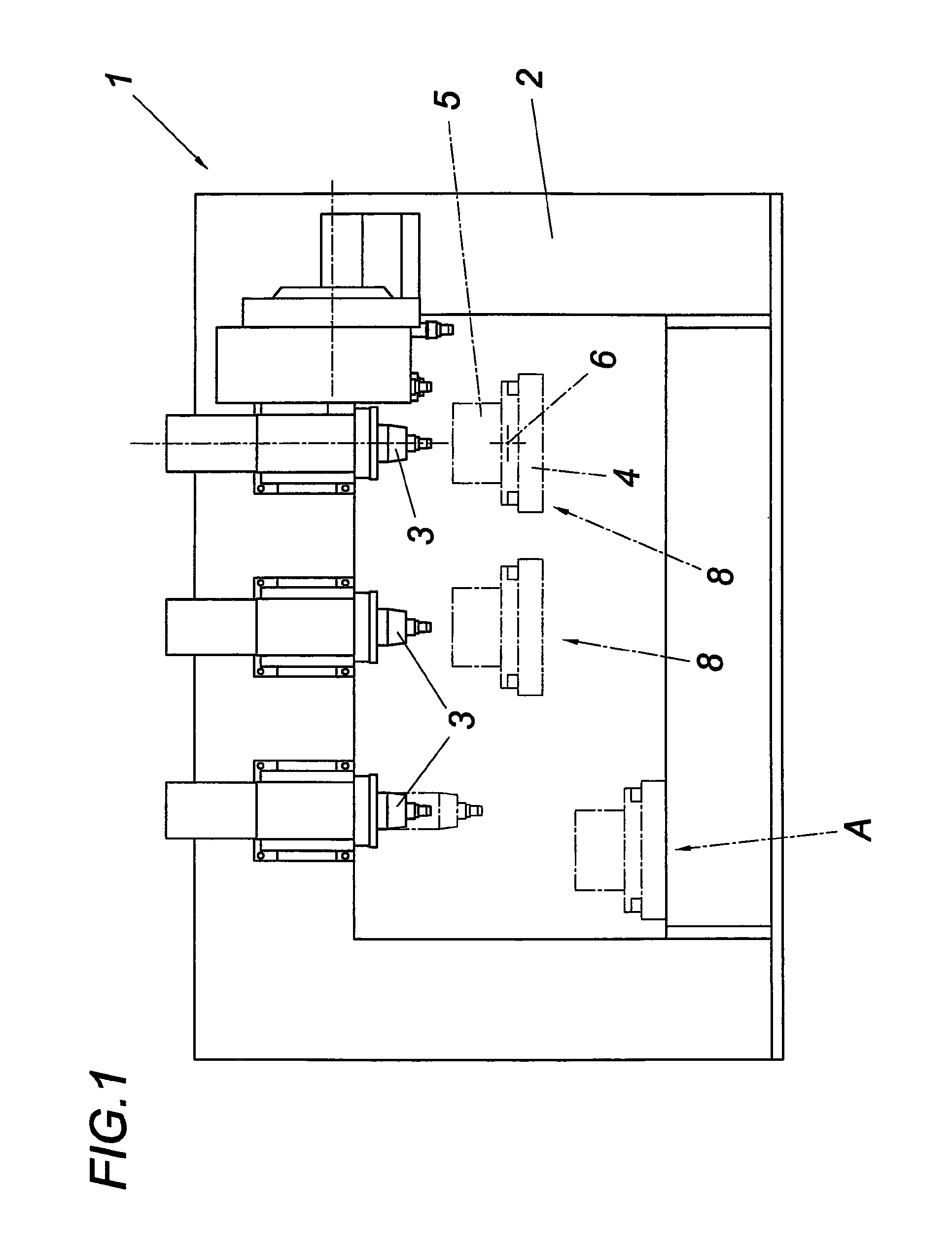
[0020]A machine tool 1 for performing the method in accordance with the invention comprises a plurality of tool spindles 3 which are arranged in a fixed manner on a rack 2 and can be positioned in different positions. It is indicated in FIG. 1 with the dot-dash line that the individual tool spindles can be movable between a retracted idle position and an extended working position in order to prevent obstructions in the machining of workpieces by other tools.

[0021]Furthermore, the machine tool 1 comprises a workpiece manipulator 4 which accommodates a workpiece 5 to be machined. Said workpiece manipulator 4 can be moved in the illustrated embodiment in a translatory manner in three axes, i.e. on the one hand in the plane of frame of rack 2 and perpendicular to said plane of the frame and on the other hand rotatably about an axis 6. It is additionally known from the state of the art to dispose the workpiece itself in a rotatably driven way on the workpiece manipulator 4.

[0022]The impl...


PUM


Abstract

The invention relates to a method for activating a workpiece manipulator (4) of a machine tool (1), comprising a control device which prescribes machining paths (6) for a workpiece by means of a computing unit, which machining paths are travelled by the workpiece manipulator (4) from a machine starting position (A), wherein the workpiece (5) which can be moved by the workpiece manipulator (4) in a multi-axially translatory and preferably also rotating manner is passed to a plurality of tools (3) one after the other for the step-by-step machining. In order to provide advantageous conditions it is proposed that in the case of termination of machining the workpiece manipulator (4) is made to move with the workpiece (5) back over the path of movement (7) assigned to the respective machining step into a position (8) prior to this machining step, in which the workpiece manipulator is optionally stopped or from which the workpiece manipulator is moved into the machine starting position (A).

Description

CROSS REFERENCE TO RELATED APPLICATIONS[0001]This application is the National Stage of PCT / AT2009 / 000304 filed on Aug. 7, 2009, which claims priority under 35 U.S.C. §119 of Austrian Application No. A 1271 / 2008 filed on Aug. 14, 2008, the disclosure of which is incorporated by reference. The international application under PCT article 21(2) was not published in English.[0002]1. Field Of The Invention[0003]The invention relates to a method for activating a workpiece manipulator of a machine tool, comprising a control device which prescribes machining paths for a workpiece by means of a computing unit, which machining paths are travelled by the workpiece manipulator from a machine starting position, wherein the workpiece which can be moved by the workpiece manipulator in a multi-axially translatory and preferably also rotating manner is passed to a plurality of tools one after the other for the step-by-step machining.[0004]2. Description Of The Prior Art[0005]With known machining tool...

Claims


Application Information

Patent Timeline
Patent Type & Authority Patents(United States)
IPC IPC(8): G06F19/00
CPCB23Q7/047G05B19/4067G05B2219/50103G05B2219/50108
Inventor HAAS, ROLANDDIRNBERGER, KLAUS
Owner ANGER MACHINING
Why Eureka
Try Eureka