
Hole punch die identification in a document reproduction system

a document reproduction system and hole punch die technology, applied in the field of hole punch die identification, can solve problems such as incompatibility of binding

Active Publication Date: 2012-05-15
XEROX CORP
View PDF15 Cites 3 Cited by
  • Summary
  • Abstract
  • Description
  • Claims
  • Application Information

AI Technical Summary

Benefits of technology

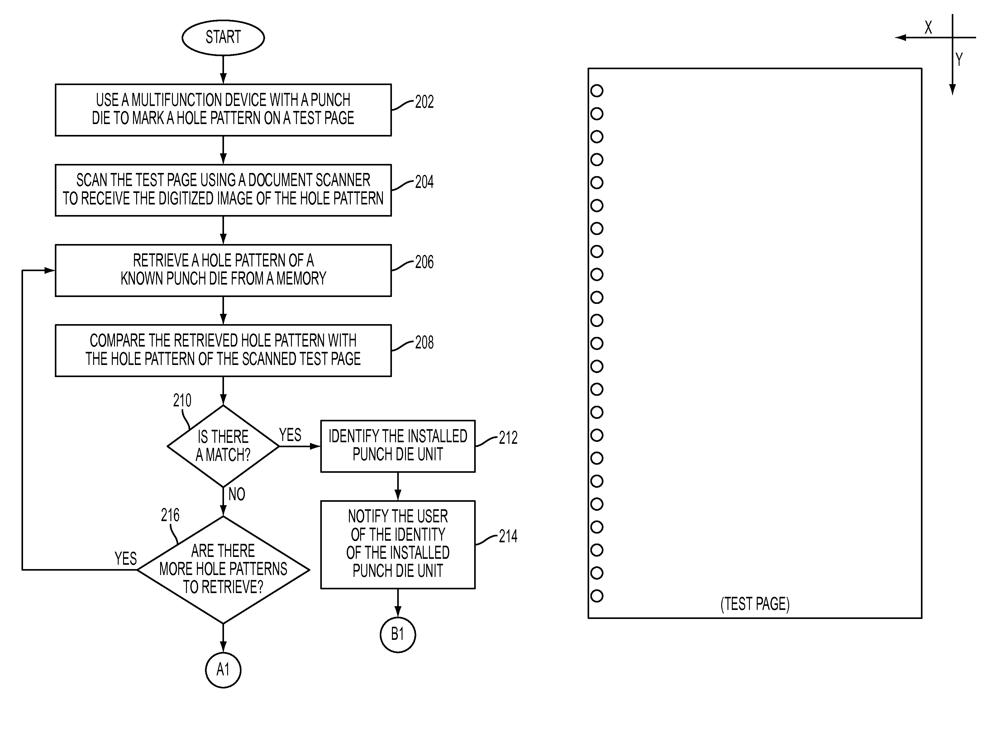
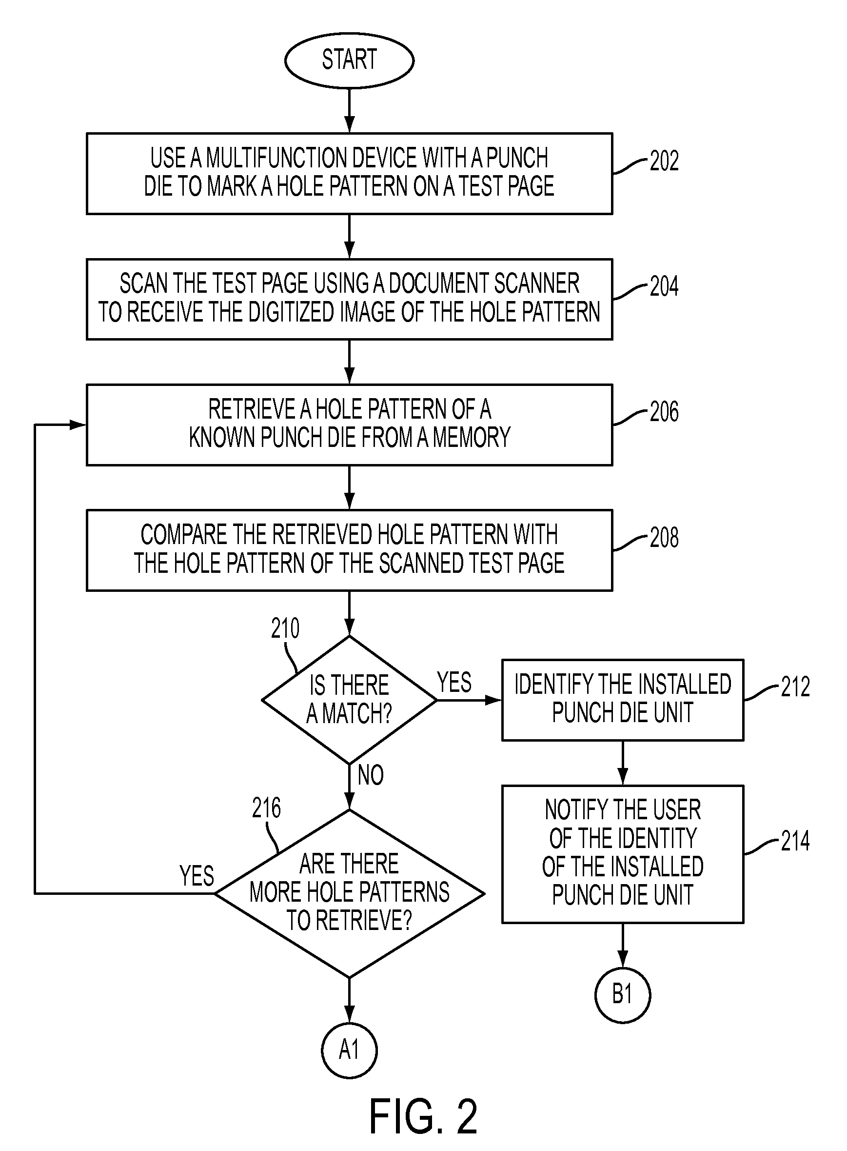
[0006]What is disclosed is a novel system and method for determining which hole punch die is currently installed on a document reproduction system. A document scanner is used to scan a sample page that has been punched by the presently installed hole punch die. The pattern of holes on the punched test page is examined and compared to known punch patterns retrieved from memory or storage. The user is provided with a notification as to the identity of the installed punch die. The method also compares the current punch die unit with bindings selected for the print / copy job. If there is a mismatch or incompatibility between the selected binding type and the installed hole punch die, the user is prevented from releasing their print / copy job to the device. The method advantageously ensures that the hole pattern of the installed punch die is correct for the binder element of the finisher.
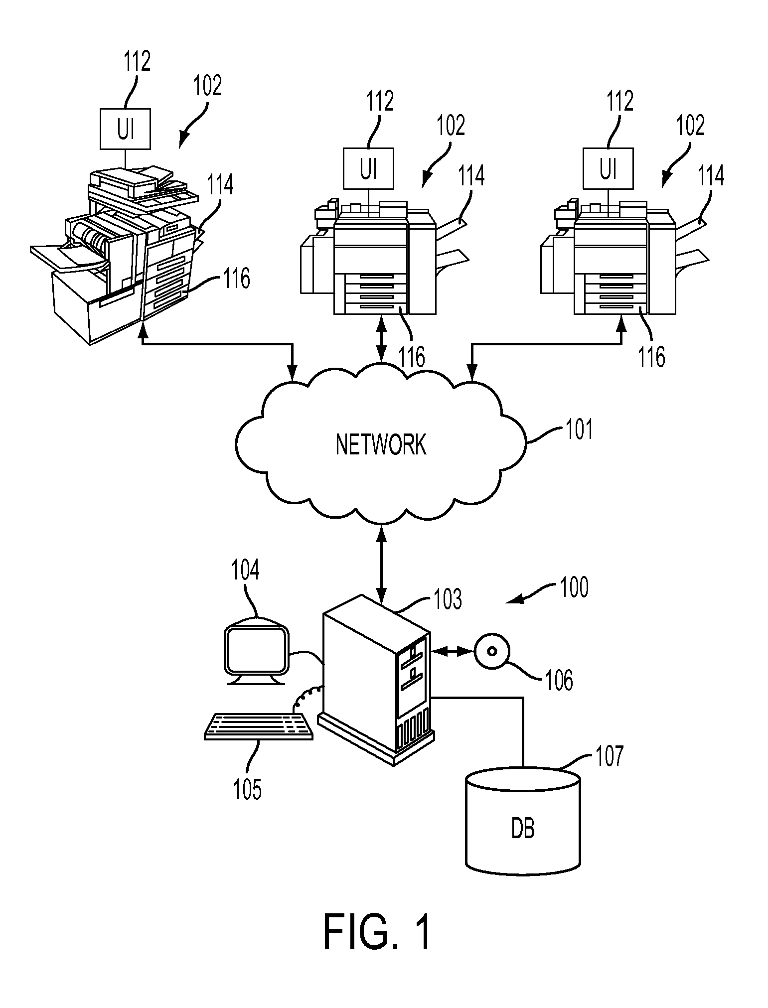
[0008]In another embodiment, information is received, from a user or a finishing device, regarding a binding type selected for the print / copy job intended to be performed on the multifunction device wherein the hole punch die is presently installed. Once the installed hole punch die has been identified, a determination is made, based on information contained in the retrieved record of the matching known die, whether the selected binding is compatible with the installed hole punch die. If not, then the user is notified that the selected binding is not compatible with the currently installed hole punch die. In one embodiment, the user is prevented from releasing their print / copy job to the multifunction device until the incompatibility has been resolved. In another embodiment, the multifunction device is prevented from operating while there is an incompatibility between the hole punch die installed and the selected binding type. Various other embodiments are provided.

Problems solved by technology

If not, then the user is notified that the selected binding is not compatible with the currently installed hole punch die.

Method used


Image

  • Hole punch die identification in a document reproduction system
  • Hole punch die identification in a document reproduction system
  • Hole punch die identification in a document reproduction system

Examples


Embodiment Construction

[0028]What is provided are a system and method for identifying which hole punch die is currently installed on a multifunction device. In an alternative embodiment, the present method ensures that the installed hole punch die is compatible with a selected finishing binder element.

[0029]It should be understood that one of ordinary skill would be familiar with many aspects of document reproduction and document finishing devices. Such an individual would perhaps be a key operator of a complex document reproduction system in a print / copy job production environment wherein various aspects of the present method find their uses. One of ordinary skill would also be knowledgeable about computer science and software and hardware programming systems and methods sufficient to implement the functionality described herein in their own document reproduction environments without undue experimentation.

[0030]An “image input device” is a device capable of capturing an image of a document. The set of im...


PUM


Abstract

What is disclosed is a novel system and method for determining which hole punch die is installed on a multifunction document reproduction device. A document scanner of a document reproduction system is used to scan a sample page that has been hole-punched by the presently installed punch die. The pattern of die holes on the punched test page is examined and compared to known punch die patterns. The method compares the current punch unit with bindings loaded in a hopper for the print / copy job. Information about the currently installed hole punch die is displayed on a graphical user interface so the user can confirm the print / copy job prior to the time of submission. The user can then accept the current hole punch configuration or change the unit to another before releasing their print / copy job. The method ensures that the selected punch pattern is compatible with other print / copy job finishing selections.

Description

TECHNICAL FIELD[0001]The present invention is directed to systems and methods for detecting and identifying a hole punch die currently installed on a document reproduction system.BACKGROUND[0002]Many print / copy jobs which are being performed in a document production environment require that the pages of the job be bound together in a manner specified by the customer. Many large print / copy production jobs require diverse bindings as part of the customer's requirements to produce financial reports, notebooks, professional surveys, sales presentations, cookbooks, calendars, to name a few. Such bindings are automatically added to the print / copy job. First, a die punches the appropriate number of holes in the right size, alignment, spacing, and configuration. The punched pages are then bound by a binder which threads the corresponding binding through the punched holes to finish the job and produce a final product for the customer.[0003]To achieve this, a technician typically loads a hopp...

Claims


Application Information

Patent Timeline
Patent Type & Authority Patents(United States)
IPC IPC(8): G06K9/62
CPCB42B5/08B42C1/00H04N1/00013H04N1/00034H04N1/0005H04N1/00063H04N1/00076H04N1/00466H04N1/00639B26F1/44G06F3/1203G06F3/1232G06F3/1285
Inventor WHITING, J. FREDERICK
Owner XEROX CORP
Learn More