
Fuel cell system and method for operating the same

a fuel cell and system technology, applied in the field of fuel cell systems, can solve the problems of reducing the conductivity of the electrolyte, deteriorating the performance and reducing the power so as to prevent the deterioration and dehydration of the electrolyte membrane and the effect of reducing the power loss of the fuel cell stack

Inactive Publication Date: 2012-05-08
SAMSUNG SDI CO LTD
View PDF24 Cites 13 Cited by
  • Summary
  • Abstract
  • Description
  • Claims
  • Application Information

AI Technical Summary

Benefits of technology

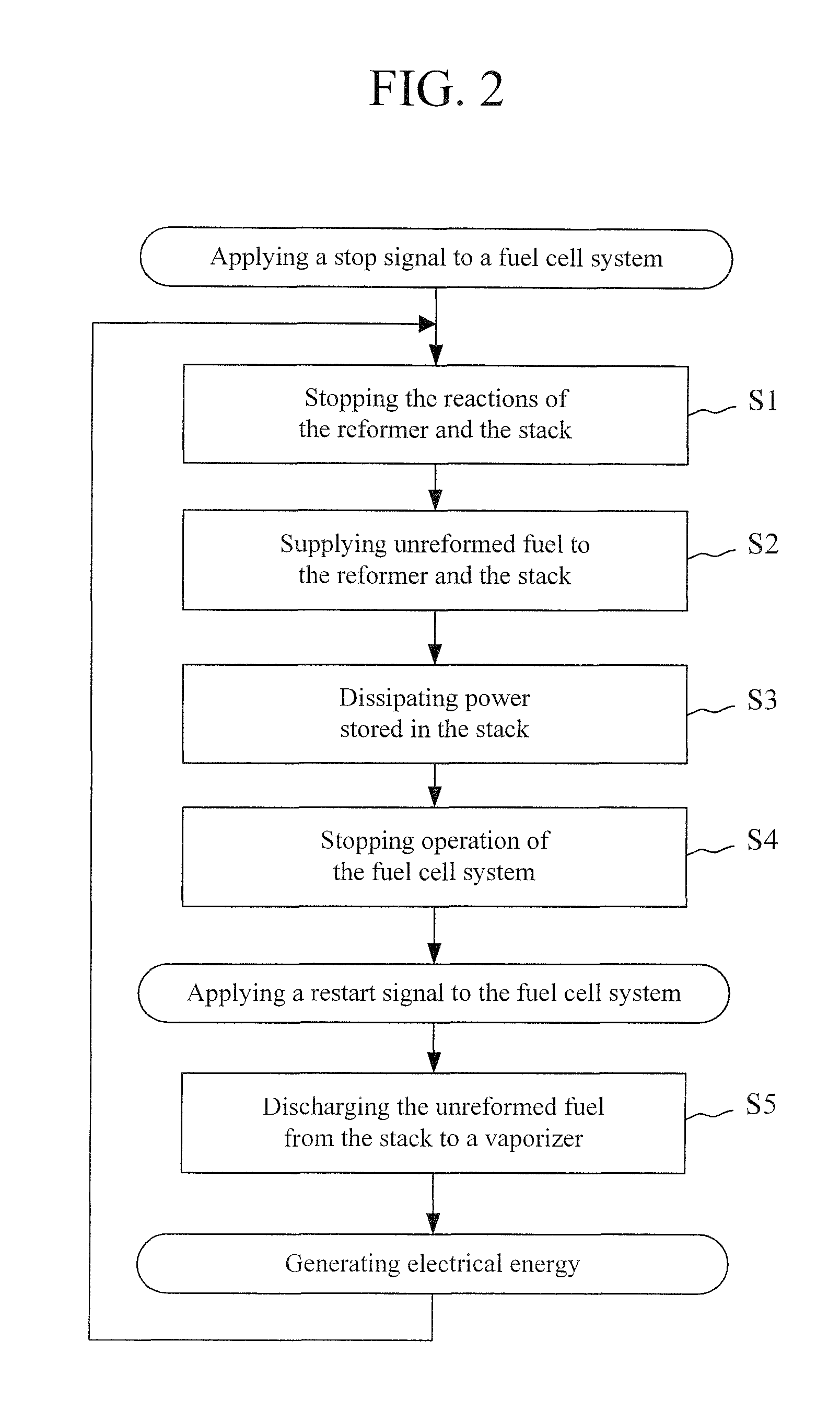
The present invention provides a fuel cell system and method for operating it that can quickly recover its performance after being stopped and then restarted. This is achieved by filling the stack with unreformed fuel and dissipating power from the fuel cell stack when the system is stopped. The fuel cell system includes a fuel supplier, a reformer, a fuel cell stack, a first valve, and a controller. The method involves stopping the reforming reaction and the electrochemical reaction of the fuel cell stack, supplying unreformed fuel to the fuel cell stack, and dissipating power from the fuel cell stack. The system can also include a power dissipation circuit and a fuel recycle conduit. The technical effect of this invention is to prevent deterioration and dehydration of the electrolyte membrane and quickly recover system performance when the system is restarted.

Problems solved by technology

This can dehydrate the electrolyte membrane of a membrane-electrode assembly (MEA) and deteriorate its performance.
This can cause a reduction in the conductivity of the electrolyte.
Therefore, system performance cannot recover quickly when the system is restarted.

Method used


Image

  • Fuel cell system and method for operating the same
  • Fuel cell system and method for operating the same
  • Fuel cell system and method for operating the same

Examples


Embodiment Construction

[0028]The present invention will be described more fully with reference to the accompanying drawings in which embodiments of the invention are shown. As those skilled in the art will realize, the described embodiments may be modified in various different ways, all without departing from the spirit or scope of the present invention.

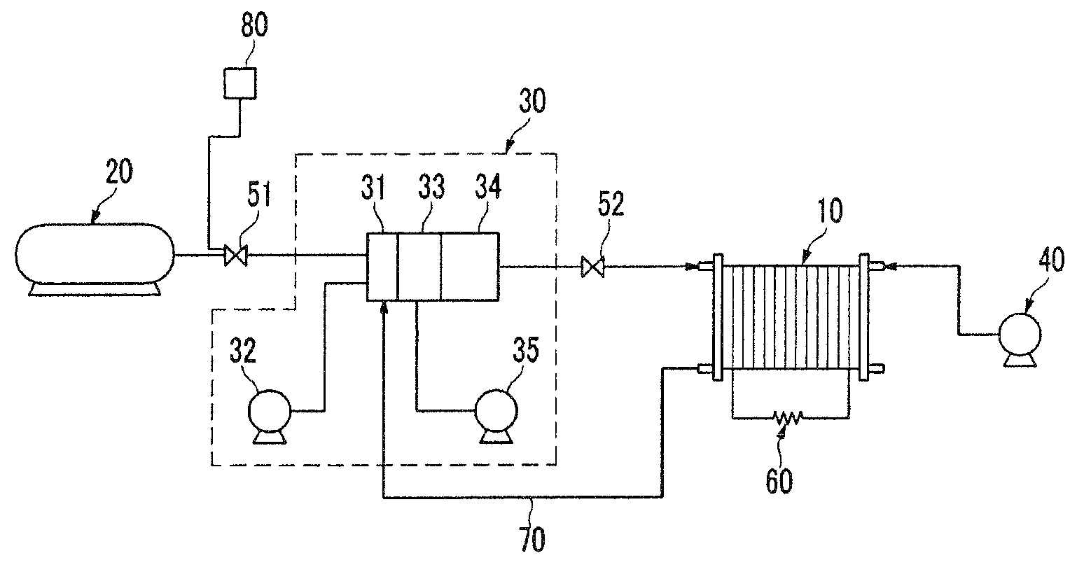
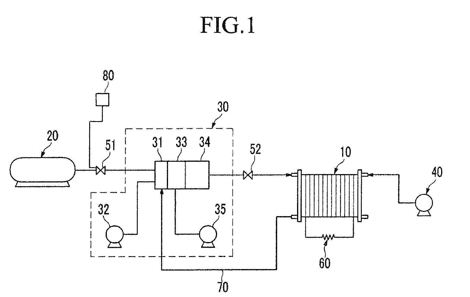
[0029]FIG. 1 is a schematic diagram of a fuel cell system according to a first embodiment of the present invention. The fuel cell system is designed such that a portion of the unreformed fuel can be provided to a fuel cell stack 10 when the fuel cell system is stopped. Deterioration and dehydration of an electrolyte membrane can be prevented. Accordingly, the fuel cell system can generate electrical energy quickly when the fuel cell system is restarted.

[0030]The fuel cell stack 10 includes a plurality of unit cells arranged in a stacked configuration with end plates on the outermost sides of the stacked unit cells. A unit cell is the minimum unit for gener...


PUM

PropertyMeasurementUnit
temperatureaaaaaaaaaa
electrical energyaaaaaaaaaa

Abstract

A fuel cell system and a method for operating the same are disclosed. In one embodiment, a fuel cell system includes a fuel supplier, a reformer for reforming a fuel supplied from the fuel supplier into hydrogen gas by a reforming reaction, and a fuel cell stack for generating electrical energy by an electrochemical reaction between the hydrogen gas and an oxidizing agent. When the fuel cell system is to be stopped, the reforming reaction of the reformer and the electrochemical reaction of the fuel cell are stopped and a portion of unreformed fuel is fed to the reformer and the fuel cell stack. Residual hydrogen is reacted and residual power from the fuel cell stack is dissipated by a power dissipation circuit. By largely removing hydrogen from the fuel cell stack on a stopped condition, reactions that are detrimental to the fuel cell membrane are reduced.

Description

CROSS-REFERENCE TO RELATED APPLICATION[0001]This application claims priority to and the benefit of Korean Patent Application No. 10-2007-0109498 filed in the Korean Intellectual Property Office on Oct. 30, 2007, the entire content of which is incorporated herein by reference.BACKGROUND OF THE INVENTION[0002]1. Field of the Invention[0003]The present invention relates to a fuel cell system. More particularly, the present invention relates to a fuel cell system and a method for operating the same on shutdown and startup.[0004]2. Description of the Related Art[0005]Fuel cells are used as electricity generating systems for generating electrical energy by an oxidation reaction of a fuel and a reduction reaction of an oxidizing agent. Such fuel cells may be classified into polymer electrolyte membrane fuel cells and direct oxidation membrane fuel cells according to the type of fuel they use.[0006]Polymer electrolyte membrane fuel cells generally have superior output characteristics, lower...

Claims


Application Information

Patent Timeline
Patent Type & Authority Patents(United States)
IPC IPC(8): H01M8/06
CPCH01M8/04231H01M8/0612H01M8/0662Y02E60/50H01M8/04H01M8/06
Inventor SON, IN-HYUK
Owner SAMSUNG SDI CO LTD
Learn More