
Second-stage regulator for scuba divers

a technology for divers and regulators, applied in underwater equipment, breathing protection, medical science, etc., can solve the problems of requiring considerable additional inhalation effort by users, affecting their ease of breathing in limited oxygen environments, etc., and achieve the effect of less inhalation effort and greater eas

Active Publication Date: 2012-05-01
CRESSI SUB
View PDF17 Cites 7 Cited by
  • Summary
  • Abstract
  • Description
  • Claims
  • Application Information

AI Technical Summary

Benefits of technology

The present invention provides a second-stage regulator for scuba divers that requires less inhalation effort by the user, making it easier to breathe in limited oxygen environments. The invention achieves this by reducing friction between mechanical members, replacing the conventional method of inhaling through an opening in the baffle with a flexible sleeve that prevents blow-by of gas and energy loss due to formation of tiny ice crystals. The invention also includes a lever that moves integrally with the tail of the poppet, negligible sliding, and a diaphragm that flexes inwardly upon inhalation, allowing the gas to pass through. The invention provides a second-stage regulator for scuba divers that significantly reduces friction between mechanical members, making it easier to breathe in limited oxygen environments.

Problems solved by technology

While conventional arrangements for second-stage regulators have been found useful, substantial friction between the interconnected mechanical actuating members, e.g., the diaphragm, lever and poppet, must often be overcome, requiring considerable additional inhalation effort by the user, thus affecting his or her ease of breathing in limited oxygen environments.

Method used


Image

  • Second-stage regulator for scuba divers
  • Second-stage regulator for scuba divers
  • Second-stage regulator for scuba divers

Examples


Embodiment Construction

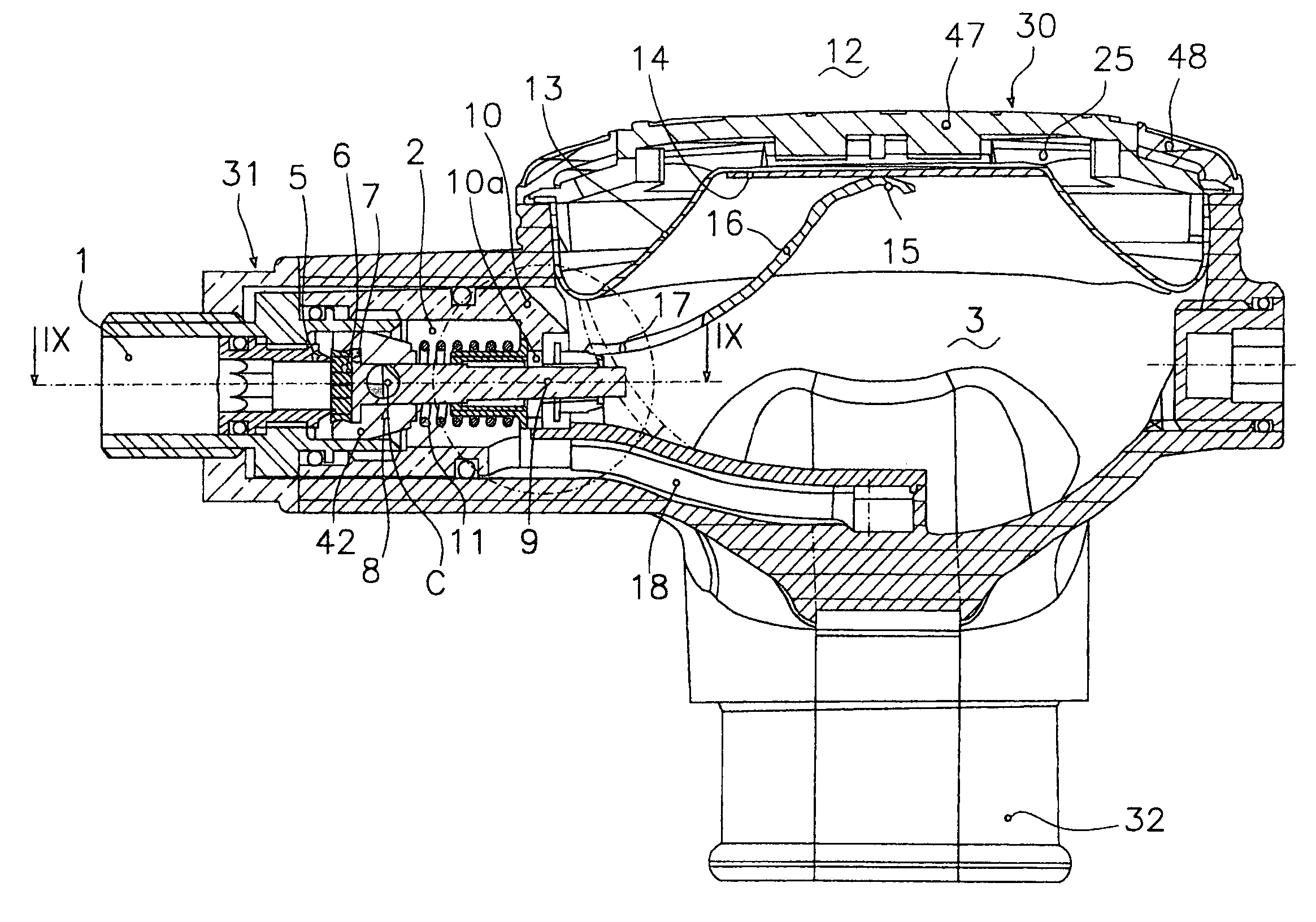
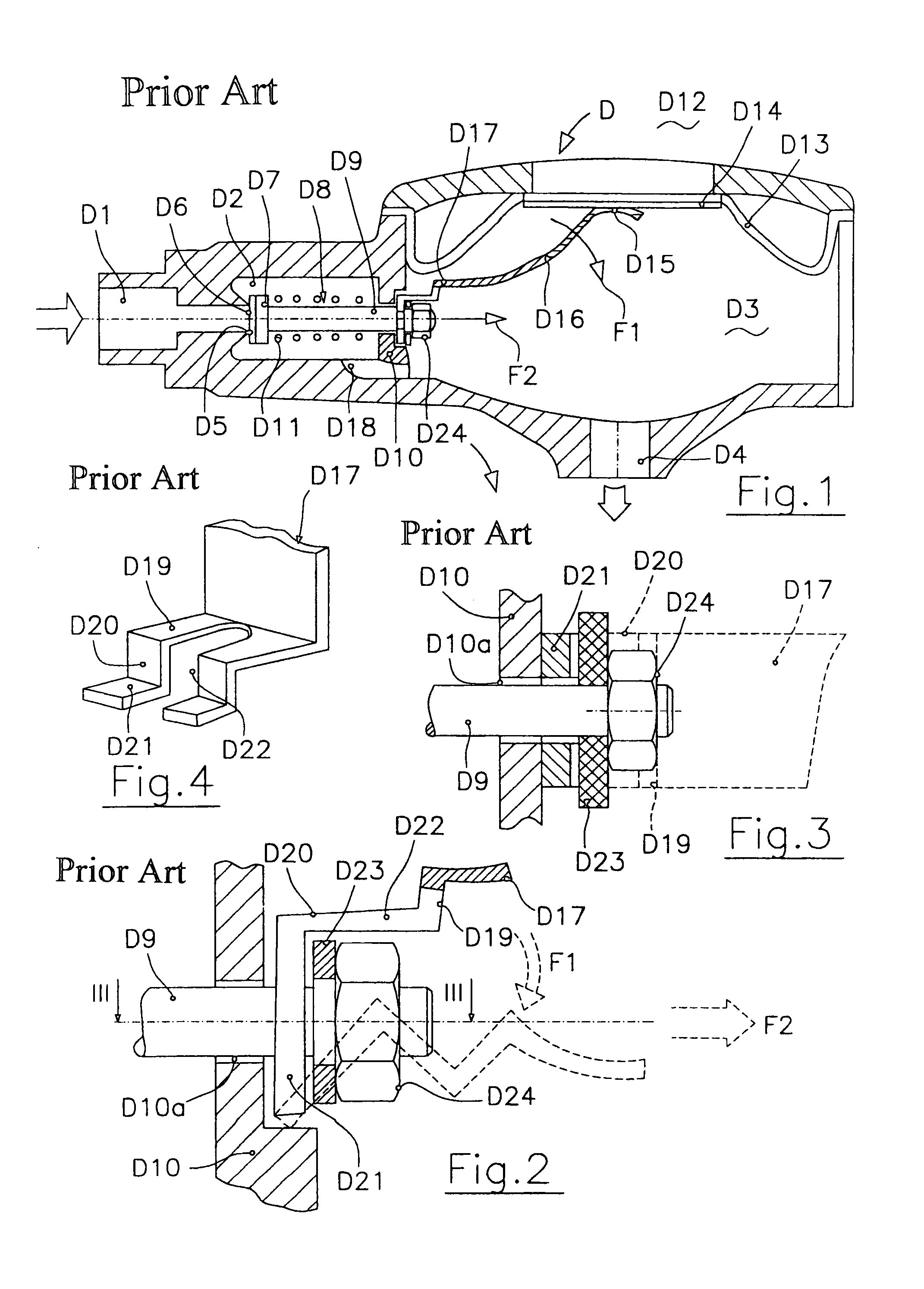
[0033]A conventional second-stage regulator D is shown, for instance, in FIGS. 1-4. The regulator has an inlet chamber D1, an intermediate chamber D2, and an outlet chamber D3 connected to a user's mouthpiece D4. Inlet chamber D1, which is at the same pressure as that of the outlet of an associated first-stage regulator, is separated from the intermediate chamber by a valve seat D5. The valve seat supports a seal D6 on a head D7 of a poppet D8. The poppet has a tail D9 passing loosely through a hole D10a in a baffle D10, between the intermediate chamber and outlet chamber. Generally speaking, a purpose of the baffle is to support a spring D11 that compresses the head of poppet D8 against valve seat D5.

[0034]The outlet chamber is separated from the external environment by a diaphragm D13. An outer end D15 of a lever D16 abuts a thin rigid plate D14 on an inner surface of the diaphragm. Another, inner end D17 of the lever is hingedly connected to the baffle and supports the tail of th...


PUM


Abstract

A second-stage regulator for scuba divers is disclosed that reduces considerably the inhalation effort required by the user through reduction in friction between selected components of the regulator. A flexible sleeve is sealingly connected to the regulator poppet and the baffle, and coaxially with the poppet, so as to avoid blow-by of gaseous mixture through an opening in the baffle. A tail of the poppet extends through the opening, the tail being connected to a lever of the regulator projecting into an outlet chamber thereof. The head of the poppet is or includes a ferrule with an at least partially-circular profile and abuts a selected inner portion of the inlet's intermediate chamber to allow oscillation of the poppet. The lever end of the regulator contacts a diaphragm, the diaphragm separating the outlet chamber from the external environment. The lever end has a generally arched shape with a profile such that the length of the arch between two adjacent contact points measured along the lever is generally equal to the length of the segment between the same adjacent contact points measured along the diaphragm.

Description

FIELD OF THE INVENTION[0001]The present invention relates generally to equipment for use in limited oxygen environments and, more particularly, to control devices for underwater activities or the like.BACKGROUND OF THE INVENTION[0002]In scuba diving, for instance, a supply of air, or of an air-oxygen mixture, is typically fed to a mouthpiece of the scuba diver from a high-pressure tank. Enroute to the diver, the air passes from a primary or first-stage pressure-reducing regulator to a second-stage regulator which, in turn, supplies the mixture to the mouthpiece, namely, when pressure within the regulator is diminished upon the diver's inhalation.[0003]Second-stage regulators typically have an inlet chamber connected to an outlet of the first-stage regulator, and an outlet chamber connected to the mouthpiece of the user. The outlet chamber is separated from the external environment by an elastically deformable diaphragm. The diaphragm is joined via a lever to a poppet which closes a ...

Claims


Application Information

Patent Timeline
Patent Type & Authority Patents(United States)
IPC IPC(8): A61M16/00A62B7/04A62B9/02F16K31/26B63C11/22
CPCB63C11/2227
Inventor PEDEMONTE, STEFANO
Owner CRESSI SUB
Learn More